
MX Road Training in India
- Real-Time Experts Sessions
- LIVE Project
- Certification
- Affordable Fees
- Flexibility
- Placement Support
MX Road is an excellent string-based modeling tool that enables the rapid and accurate design of all types of roads. Individuals such as civil engineers, designers, surveyors, system designers can access 3D modeling, construction driven engineering, and other analysis all in one engineering application. MX Road contributes to improving the quality of designs by combining traditional engineering workflow profile and cross sections with 3D modeling technology.
Applications
This course of MX Road aims to help you excel various features of the software, such as Interoperable Database that means creation and annotation of 3D project models. It will also help you to learn digital terrain model creation and integration with Google Earth.
Civil
Course Highlights:
MX Road Foundation :
- Creation of road plan
- Types of drawings
- Edit models
- 2D to 3D view surface
- Create advance model
- Carriageway design
- Junction design
- Pavement and subgrade design
- Dynamic reports
- Final drawing
MX Road Advanced :
- Surface analysis
- Dynamic surface analysis
- Pavement and subgrade design
- Design- alignment by element method
- Design- Vertical profile
- Road design- shoulder design
- Road design- kerbs, verges and footways
- Earthwork design
- Overlay design -Template method
- Road Re-design and Rehabilitation
- Testing a design
- Isopach analysis
Duration :
- 45 Hours Theory
- 25 Hours Practical
- 30 Hours Project work
Foundation Technical Features:
Creation of a road plan
MX Road is an advanced string-based modelling tool that enables all road types’ rapid and accurate design We can quickly create sign alternatives with MX Road to build an ideal road system. Once a final alignment the alternative is selected, we can automate much of the design detailing process, saving time and money.

Edit models
Built-in CAD Capabilities – Standalone full MicroStation with read/write any version of DGN/DWG files
Integrated Mapping – Bentley Map is included for data interoperability and generates reports
Survey/Data Acquisition – Read/write the RAW survey, reference images/point cloud with edit option
Terrain Model Creation & Editing – Import/export 3D data (XML, LiDAR, aerial and native formats), Analysis and edit, visual presentation and triangulation.
Geometry – 3D complete geometry with full report for horizontal/vertical alignment.
Corridor modelling – Full package with a customizable template for urban/rural tunnel/retaining wall design.
Drainage Layout and Design – 3D drainage modelling with an interconnected network of pipes, channels, culverts, manholes etc.
Quantity Management – Full volume reports with various export options to CSV, HTML or pdf.
Output/Publishing – Localized JKR/REAM full drawing production. Option available to export to drawing or to pdf to scale.

Types of drawings
Before starting the wizard, it may be advisable to open a journal file to capture the MX commands used to create the shoulder design. This journal file (with some editing) can be run to reproduce the design, when necessary, without having to use the wizard again.

2D to 3D view surface
Object-based CAD technologies concentrate on simulating building components on a CAD platform. They help in extracting quantity data and 2D documentation from construction parts. Furthermore, they can also support the automatic generation of various drawings such as cross-sections and longitudinal profiles based on routines that use 2D CAD entities. Certain 3D views can be obtained as a result of data processing in multiple 2D views. They can be considered BIM-compatible because they usually contain information about the designed infrastructure.

Create advance model
design controlling parameters such as design speed, horizontal curvature, superelevation and
vertical curvature can also be effectively designed and controlled by MXROAD software.
- Design of Road Pavement
- Creating Cross Sections on MX Road
- Creating Long Sections on MX Road
- Report Generation
- Saving the Models into Input Format
- Creating Offsets using Input Files
- Creating Cross Sections and Long Sections using Input Files
- Creating a Curve Table on MX Road

Carriageway design
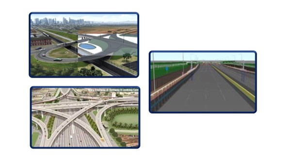
one of the two sides of a motorway where traffic travels in one direction only usually in two or three lanes. expressway, freeway, motorway, pike, state highway, superhighway, throughway, thruway – a broad highway designed for high-speed traffic.

Junction design
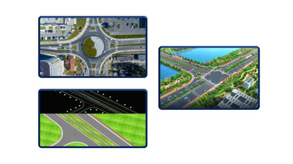
Road Junctions are designed at places where vehicular traffic can systematically move in different directions. Road Junctions decrease the probability of accidents. The traffic at Road junctions is controlled and resumed in a systematic way to proceed further in their respective directions with the help of traffic signals.The design of Road Junctions is a crucial subject. Understanding the nature of traffic, the kind of area, population density, etc is very important to propose a suitable road Junction design.
- T-Junction
- Y-Junction
- Acute Angle Junction
- Staggered Junction
- Multiple Junction
Pavement and subgrade design
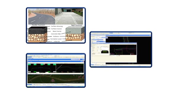
A highway pavement is a structure consisting of superimposed layers of processed materials above the natural soil subgrade, whose primary function is to distribute the applied vehicle loads to the subgrade. The pavement structure should be able to provide a surface of acceptable riding quality, adequate skid resistance, favourable light-reflecting characteristics, and low noise pollution. The ultimate aim is to ensure that the transmitted stresses due to wheel load are sufficiently reduced so that they will not exceed the bearing capacity of the subgrade.
Two types of pavements are generally recognized as serving this purpose, namely
- flexible pavements
- rigid pavements.

Dynamic reports
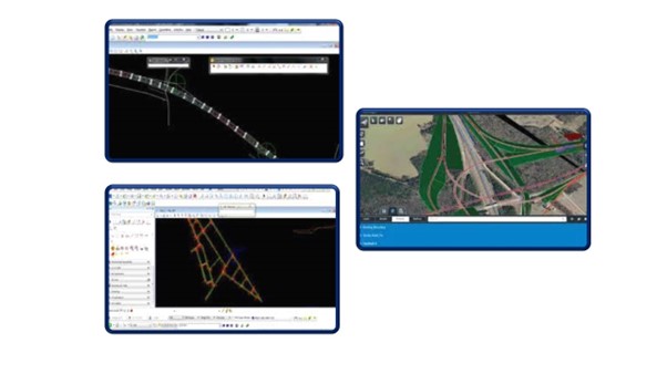
The process of generating an offset report begins by selecting the Normal Intersection option from Geometric Reports on the Report menu. Select the model and string names for the reference string and the one being compared. At each point on the reference string, MX will report the offset and elevation difference of the second string. If an exact point does not exist on the second string, one will be interpolated.
Final drawing
civil engineer highway engineering auto cad structural design civil building design construction design manager highways infrastructure projects project management electrical engineering water civil engineering road design drainage.
- As an engineer, your responsibilities include Planning, Monitoring,
- Conducting traffic, topographic, material investigation surveys,
- Junction/Road Inventory surveys and Geometric design of roads, Cost estimation,
- Data analysis, Detail Design on Civil 3D and MX Road and Report preparation. Advanced Level Knowledge of Excel is added advantage.
Advanced Technical Features:
Surface analysis
Go into Analysis>Surface Analysis and pick the model you want to analyse. It triangulates it in the background and then shows you all the Analysis Options. The bottom one is Catchment Area.
It now works out from the triangulation, where all the catchment areas are for this particular surface and creates boundary strings around each area. You can click on the display and it highlights that area in a colour and shows the flow arrows.

Dynamic surface analysis
This option is used for analysing the surface on which the design has to be built. This is essential to confirm that the imported data is correct and contains no errors. Typically, the analysis will highlight errors in level and will also provide a graphical representation of the existing surface.

Pavement and subgrade design
A highway pavement is a structure consisting of superimposed layers of processed materials above the natural soil subgrade, whose primary function is to distribute the applied vehicle loads to the subgrade. The pavement structure should be able to provide a surface of acceptable riding quality, adequate skid resistance, favourable light-reflecting characteristics, and low noise pollution. The ultimate aim is to ensure that the transmitted stresses due to wheel load are sufficiently reduced so that they will not exceed the bearing capacity of the subgrade.
Two types of pavements are generally recognized as serving this purpose, namely
- flexible pavements
- rigid pavements.
Design- alignment by element method
The intention of this study is to import road geometric design into the software as well as relate it with the design standards applied to the software. It will be able to design road geometric by checking survey data, horizontal and vertical design, super-elevation and production of road cross sections. Bentley MXROAD is an advanced, string-based modelling tool that enables the rapid and accurate design of all road types. With MXROAD, At its core, MX ROAD uses 3D string modelling technology. A powerful yet concise method of creating 3D surfaces

Design- Vertical profile
- Survey model or Ground model
- Design model showing the proposed layout
- GDS model – Geometry Data Store – for alignment design
- The triangulation model represents models as surfaces
- Contour model to store contours of those surfaces
- Section model to store longitudinal and cross sections through those surfaces.

Road design- shoulder design
The intention of this study is to import road geometric design into the software as well as relate it with the design standards applied to the software. It will be able to design road geometric by checking survey data, horizontal and vertical design, super-elevation and production of road cross sections. Bentley MXROAD is an advanced, string-based modelling tool that enables the rapid and accurate design of all road types. With MXROAD, At its core, MX ROAD uses 3D string modelling technology. A powerful yet concise method of creating 3D surfaces

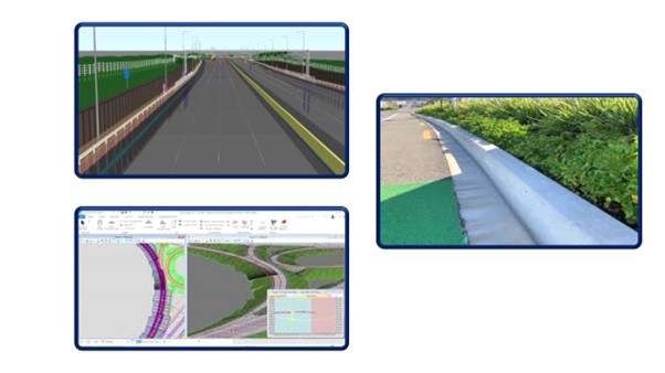
Road design- kerbs, verges, and footways
A Kerb has the following functions
- Protection of Pedestrians from higher-speed vehicles
- Guiding traffic along the edge
- Control/ regulation of Drainage
Design Precautions:
- Prevention of overturning of vehicles on faster roads
- Prevention of jaywalking on thoroughfare roads
- Prevention of Parking on footpaths
verges-A road verge is a strip of grass or plants, and sometimes also trees, located between a roadway (carriageway) and a sidewalk (pavement). Verges are known by dozens of other names, often quite regional; see Terminology below.
Walking is fundamental to urban life. It is a healthy and pollution-free form of mobility and recreation. Pedestrian trips account for a quarter to a third of all trips in many Indian cities. However, the poor quality of pedestrian infrastructure sends a message that pedestrians are not welcome in the urban environment.
Footpath-A footpath is a type of route designed just for pedestrians and not for other types of traffic such as cars or bicycles. Footpaths are found in a range of locations, including city centres, farms, and mountain ridges.
Earthwork design
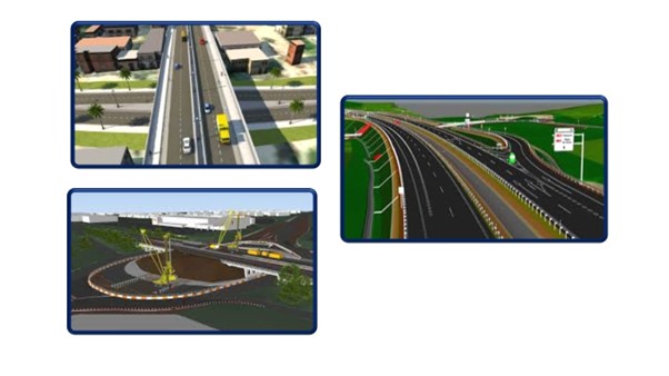
There are two methods for generating Level Datum strings for earthwork computations. The method one chooses to use ultimately depends on the proposed shoulder cross slope. Most road designs will require using both methods. Larger projects, specifically those containing reversing curves, will likely require constructing a segmented earthworks datum string as constraints are likely to evolve from beginning to end. Only one side of a roadway can be done at a time

Overlay design -Template method
A well-compacted pavement section or one which has been well condition by trafficked forms elastically under each load application Such that when the load moves away, there is an elastase cover or Rebound deflection of the deformed pavement surface. Maximum deflection depends upon subgrade soil properties, moisture in the subgrade, pavement thickness sandpits composition, temperature of pavement etc

Road Re-design and Rehabilitation
This liaison resulted in the development of new and numerous improvements to design documents and specifications such as those contained in the Technical Recommendations for Highways (TRH) documents that addressed technical aspects covering a wide range of related aspects within the road management, design, maintenance and rehabilitation environment. The draft TRH12 series of documents specifically addresses project-level flexible road pavement rehabilitation investigations and design.
Testing a design
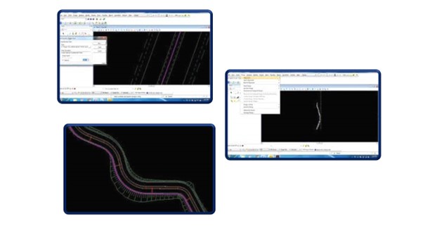
Isopach analysis of the alignment design option is used to create the alignment for the road design by choosing the Quick alignment option, Horizontal Design, and Vertical profile can be done in a limited time duration. The alignment is converted to a mistreating which is generally used as the Centreline along which carriageway and other features can be designed. Alignments are created in two stages. presents the screenshots of various geometric design elements of the road selected for the case study using Mx Road software.
Upcoming Batches
Certifications

MX Road Certification Training
About MX Road Certification Training in Indore at Tech Cluster
Reviews


