
E-TABS Training in India
- Real-Time Experts Sessions
- LIVE Project
- Certification
- Affordable Fees
- Flexibility
- Placement Support
The company develops and delivers data visualization and report automation software and services tailored for the market research industry. The company was established in 1993 as ISPC by one of the original founders of Quantime- a specialist Data Processing software. Following a management buyout in 1999 ISPC was rebranded as E-Tabs
Applications
E-Tabs software automatically populates charts, graphs and reports in Power Point , Excel, Word and HTML. Their products and services are used in market research as research projects often involve reporting work. Automating charts, graphs and reports improves accuracy and prevents time and resources being wasted on data entry
Report automation is beneficial for projects with repetitive elements, tracking studies, ongoing studies, one-off multi-segment studies across brands or regions, and concept testing studies.
Civil
Course Highlights:
E-Tabs Foundation:
- Accurate Elastic Shortening Computation.
- Modified wall Panel & Meshing.
- Automated load combination
- Buckling & Push Over & P-Delta Analysis
- Design of concrete structure
- Design of steel structure
- PEB structure analysis
- 3D Structure Modelling.
E-Tabs Advanced :
- Buckling & Push Over & P-Delta Analysis
- Design Of Retaining Structure
- Pre-engineered building analysis
- Design Of Building Elements
- Design of steel structure (IS 800 2007 LSD/WSD)
- Design of RCC structure (IS 456)
- Wind analysis of building (IS 875 Part 3)
- Seismic analysis on structure (IS 1893 2002/2005)
- Analysis and report
Duration :
- 45 Hours Theory
- 25 Hours Practical
- 30 Hours Project work
Technical Features:
E-Tabs Foundation:
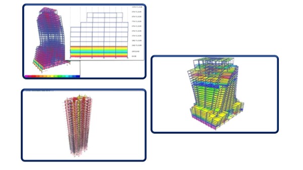
Accurate Elastic Shortening Computation
Elastic Shortening, ΔfpES (S5.9.5.2.3)
The prestress loss due to elastic shortening of pre-tensioned members is taken as the concrete stress at the centroid of the prestressing steel at transfers, multiplied by the ratio of the modulus of elasticities of the prestressing steel and the concrete at transfer.
This is presented in Eq. S5.9.5.2.3a-1.
ΔfpES = (Ep/Eci) fcgp (S5.9.5.2.3a-1)
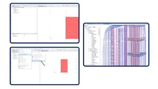
Modified wall Panel & Meshing
• Click the Draw menu > Draw Floor/Wall Objects > Draw Wall Openings command or button to add an opening to the wall.
• You can lock dimensions while in the Properties of Object form. Make sure that snap increments via Draw > Snap Options are in line with specified opening dimensions so that the exact dimensions as entered in The properties of Object form can be reflected in the model.
Automated load combination
The same can be extended to deformations. If you look for the deformed shape of an envelope, it will show the extreme values of displacements at all the points and they may not occur simultaneously.
It is suggested to analyze the deformed shape for a particular combination but not the envelope. But to get the maximum values of the displacement you can turn to the envelope.

Buckling & Push Over & P-Delta Analysis
BUCKLING -Linear (bifurcation) buckling modes of a structure can be found under any set of loads. Buckling can be calculated from a nonlinear or staged-construction state.
P-delta analysis captures the softening effect of compression and the stiffening effect of tension. A single P-delta analysis under gravity and sustained loads can be used to modify the stiffness for linear load cases.

Design of concrete structur
The seminar topic “Design of an RCC structure using ETABS”, starts with drafting a plan for building in AUTO CADD software. After completion of the drafting process, the design of the slab, beam, and column is to be done. The material to be used in the structure is to be defined too

Design of steel structure

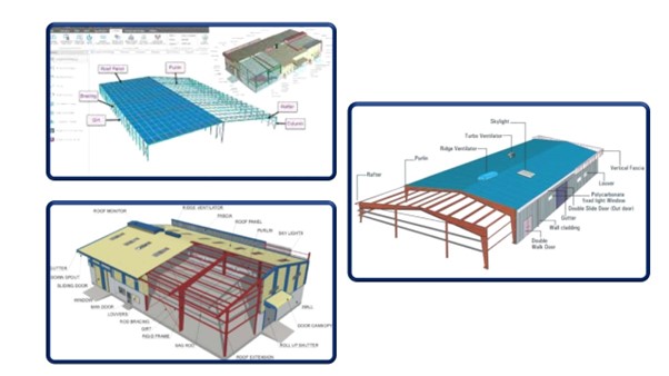
PEB structure analysis
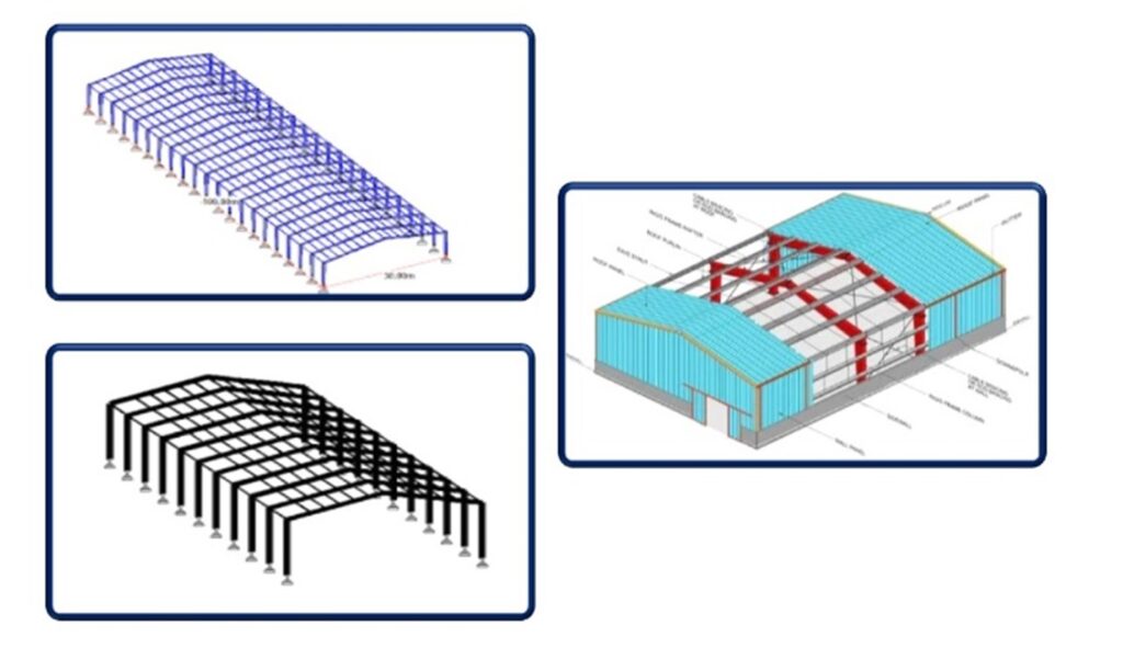
Pre-engineered buildings are generally low-rise buildings however the maximum eave height can go up to 25 to 30 meters. Low-rise buildings are ideal for offices, houses, showrooms, shop fronts, etc. The application of the pre-engineered buildings concept low -risers buildings is very economical and speedy. Buildings can be constructed in less than half the normal time, especially when complemented with the other engineered sub-systems.
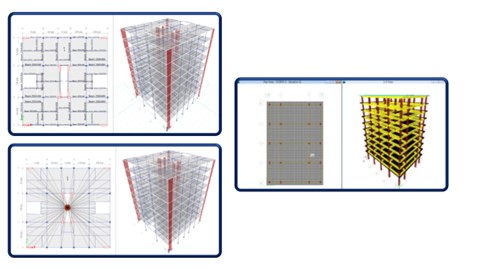
3D Structure Modelling.
Fundamental to ETABS modeling is the generalization that multi-story buildings typically consist of identical or similar floor plans that repeat in the vertical direction. Modeling features that streamline analytical-model generation, and simulate advanced seismic systems, are listed as follows:
• Templates for global-system and local-element modeling
• Customized section geometry and constitutive behavior
E-Tabs Advanced:
Buckling & Push Over & P-Delta Analysis
Pushover is a static-nonlinear analysis method where a structure is subjected to gravity loading and a monotonic displacement-controlled lateral load pattern which continuously increases through elastic and inelastic behaviors until an ultimate condition is reached. The lateral load may represent the range of base shear induced by earthquake loading, and its configuration may be proportional to the distribution of mass along building height, mode shapes, or other practical means.

Design Of Retaining Structure

Pre-engineered building analysis
Pre-engineered buildings are generally low-rise buildings however the maximum eave height can go up to 25 to 30 meters. Low-rise buildings are ideal for offices, houses, showrooms, shop fronts, etc. The application of the concept of pre-engineered buildings to low-rise buildings is very economical and speedy.
Frames
Secondary Members-
Steel Standard Buyouts (SBO)
Design Of Building Elements
Concrete Frame Design
Concrete frame design in ETABS includes the required area of steel calculations, auto-selection lists for new member sizing, implementation of design codes, interactive design, and review, and comprehensive overwrite capabilities.
Shear Wall Design
Composite Beam/Column Design
Concrete Slab Design

Design of steel structure (IS 800 2007 LSD/WSD)
Design of RCC structure (IS 456)
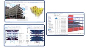
When using the ETABS software as your tool for analysis and design in your project on-hand, you must equip with thorough knowledge and understanding in every aspect and stage from modeling to analysis to design of each structural member. Each stage has its technique and guidelines to make our ETABS model as accurate as possible and free of warning and error messages.

Wind analysis of building (IS 875 Part 3)
the IS 875-3: 2015, the design wind speed for the location and the design wind pressure for the rectangular building with pitched roof can be solved using the equations below:
Design wind speed at height z (in m/s): Vz = Vbk1k2k3k4 (1)

Seismic analysis on structure (IS 1893 2002/2005
Analysis and report
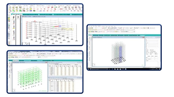
Once modeling is complete, ETABS automatically generates and assigns code-based loading conditions for gravity, the seismic, wind, and thermal forces. Users may specify an unlimited number of load cases and combinations.
Analysis capabilities then offer advanced nonlinear methods for the characterization of a static pushover and dynamic response. Dynamic considerations may include modal, response-spectrum, or time-history analysis.

Upcoming Batches
Certifications

E-TABS Certification Training
About E-TABS Certification Training in Indore at Tech Cluster
Reviews


