


TEKLA Training in India
- Real-Time Experts Sessions
- LIVE Project
- Certification
- Affordable Fees
- Flexibility
- Placement Support
Tekla is a software product family that consists of programs for analysis and design, detailing and project communication. Tekla software is produced by Trimble, the publicly listed US-based technology company.
Structural design engineers, detailers, fabricators, contractors and project managers can create, combine, manage and share accurate models for every project. Work with any material,
Engineers can seamlessly combine design and analysis with just one robust, user-friendly single-model-based process. Build beyond limits, work with any material, and deliver safe, effective, and rationalized design faster than ever before.
Engineers can automate civil and structural calculations for speed, accuracy, and peak performance. Wave goodbye to tedium and hold projects in the palm of your hand. This powerful and easy-to-use analysis software gives you flexibility and freedom.
Application :
Civil
Course Highlights:
TEKLA Structures:
• Introduction
• Understanding of plans, structural terms
• Application or use of software
• TEKLA user interface
• Detailed study of commands
• Geometry creation
• Different types of model creation
• Structure element properties
• Understanding of loads and moments
• TEKLA detail understanding of menu
• Application of results and structural drawings
TEKLA Advance: :
• Structural Loads calculation
• Bridge design
• Creation of complex structure
• Joints and connection studies
• Joints and connection design
• Design of steel structure (IS 800 2007 LSD/WSD)
• Wind analysis of building (IS 875 Part 3)
• Seismic analysis on structure (IS 1893 2002/2005)
• Analysis and report creation
Duration :
- 45 Hours Theory
- 25 Hours Practical
- 30 Hours Project work
Technical Features:
E-Tabs Foundation:
Introduction
Tekla is software engineering company specialized in model-based software products for building, construction and infrastructure management The company was listed on the Helsinki Stock Exchange from May 2000 until February 2012. The name Tekla is a given name, used in the Nordic countries, in Poland and in Georgia. However, in this case it is an abbreviation of the Finnish words Teknillinen laskenta, which means technical computation.
Understanding of plans, structural terms
• To Analyse gravity and lateral load
• Check designs for code
• Design & Analyse with finite elements
• Integrating steel connection designs
Application or use of software
• Design of steel structure as per the codes of selected countries
• It is capable of analyzing and designing civil engineering structures such as buildings, bridges, towers, cranes, high rise buildings etc.
• Improve multi-discipline team collaboration through desktop and cloud and mobile applications
• This software can generate loads (wind and earthquake) as per building codes of selected countries.
• It has an open architecture
• It has user-friendly package and graphical user interface.
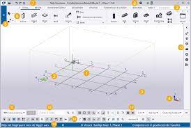
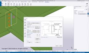
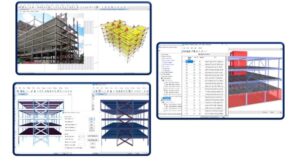
TEKLA Structure User Interface
When you open a Tekla Structures model, a new window appears. By default, the user interface will look something like this:
(1) This is your Tekla Structures model. If you are starting a completely new project, you will only see the default model view and an empty grid at this point.
(2) The green cube symbol represents the global coordinate system and it lies at the global origin (x=0, y=0, z=0).
(3) The box around the grid represents the work area. In a view, you can only see the parts that are within this area. Objects that are outside the work area exist in the model, but they are not visible. You can shrink and expand the work area to suit your needs. You can also hide the work area box.
Application or use of software
• Design of steel structure as per the codes of selected countries
• It is capable of analyzing and designing civil engineering structures such as buildings, bridges, towers, cranes, high rise buildings etc.
• Improve multi-discipline team collaboration through desktop and cloud and mobile applications
• This software can generate loads (wind and earthquake) as per building codes of selected countries.
• It has an open architecture
• It has user-friendly package and graphical user interface.
Detail study of commands
• work with grids and views
• define the work area and coordinates that affect your work
• zoom and rotate the model
• create, select and move objects
• position objects by using snapping
• filter objects both in the modeling mode and in the drawing mode.

Set up the workspace
• Define the units and decimals you will use.
• Modify the grid to suit your needs. Create a modular grid if needed.
• Create some views to examine the model from different angles and elevations.
• Resize the work area to suit your project.
• Get familiar with the coordinate system. If you are modeling sloped structures, shift the work plane accordingly.
Change the unit
• On the File menu, click Settings > Options, and go to the Units and decimals settings.
• Modify the units and decimals to suit your needs.
• The number located to the right of each option indicates the number of decimals. The number of decimals affects the input and storage accuracy. Always use a sufficient number of decimals
• Click OK to save the changes.
Work with grid
A grid represents a three-dimensional complex of horizontal and vertical planes. The grid is shown on the view plane using dash-and-dot lines. You can create both rectangular and radial grids. Use grids as an aid in locating objects in a model. You can make rectangular grids and grid lines act magnetically so that the objects on the grid lines of a rectangular grid follow if you move the grid line.
Grid terminology
Several grids in one model
Single grid lines
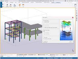
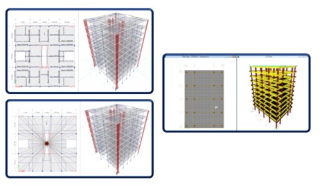
Analyze model
When you create an analysis model, Tekla Structures generates the following analysis objects and includes them in the analysis model:
• Analysis parts, bars, members, and areas of the physical parts
• Analysis nodes
• Support conditions for nodes
• Rigid links between the analysis parts and nodes
• Loads to analysis parts
Structure analysis work flow in TEKLA STRUCTURE-
1. Set the load modeling code.
2. Create load groups.
3. Create loads.
4. Create filters for selecting and adding objects to the analysis model, and for defining secondary analysis parts and braces.
5. Create a new analysis model of the selected parts and loads using the filters you created.
6. Check the analysis model and analysis parts in a Tekla Structures model view, and make modifications if needed.
7. Add the primary beams and other needed objects to the same analysis model.
Combine Loads
Load combination properties define how Tekla Structures combines loads. The following properties control the load combination process:
• Load modeling code
• Load combination factors
• Load combination types
• Load group compatibility
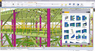
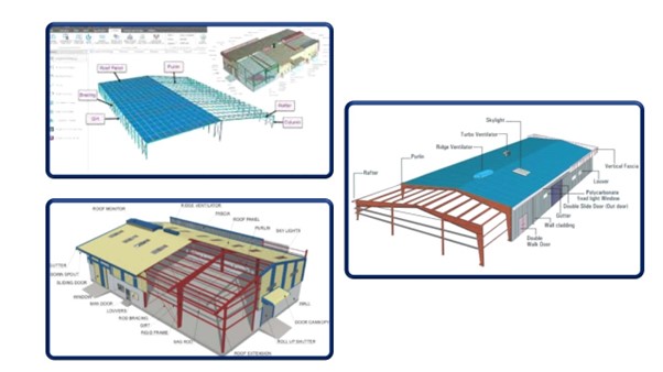
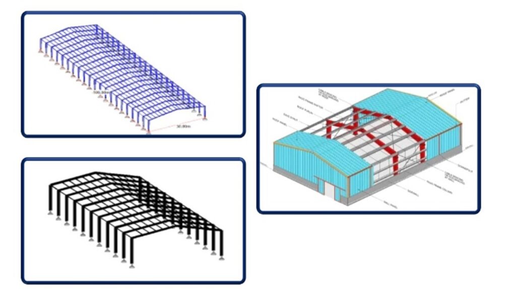
System Components
Steel components-
• Shear tab connections
• Clip angle connections
• Bent plate connectionsE
• End plate connections and details
• Splice connections
• Joist connections
• Welded connections
• Seated connections
• Opening connections
• Bracing
• Tubes
System Components
Concrete components-
• Concrete detailing
• Reinforcement
• Automated Reinforcement
Understanding of loads and moments
• Design & Analyze with finite elements
• Design beams, columns, and walls
• Design lateral resisting frames
• Generate design loads and load combinations
• Integrating slab & foundation designs
• Integrating steel connection designs
• Model reinforced concrete
• Produce structural design documentation
• Model structural steel
Application of results and structural drawings
• Check designs for cold-formed sections
• Comply with seismic requirements
• Create finite element meshes
• Design & analyses with finite element meshes, structural model
• Design beams, columns, walls and resisting frames
• Design to international design standards
• Loads and load combinations
• Integrate slab and foundation designs
• Model reinforced concrete, steel
• Structural design documentation
• Share structural models
• Save time with automation
Advanced Technical Features:
Structural Loads calculation
The loads in buildings and structures can be classified as vertical loads, horizontal loads and longitudinal loads. The vertical loads consist of dead load, live load and impact load. The horizontal loads consist of wind load and earthquake load.

Advance Foundation design
STAAD Foundation Advanced is a comprehensive structural foundation design and analysis software that includes specialized features for foundations of many types.
• Stepped footing
• Combined footing
• Isolated footing
• Pile foundation

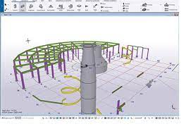
Simultaneous control of your Analytical and Bridge Information models.
Are you frustrated at having two separate models during the design stages of your bridge? Imagine having one single point of control to manage your Analytical Model and Bridge Information Model (BrIM).
Now it is possible for any type of bridge – simple or complex, steel, concrete or even timber. There is no more need to keep updating the two models. FEM and BIM are connected at last. Now there is an out of the box workflow available for any type of bridge.
Real-time efficient changes and avoided errors
Any change made in SOFiSTiK or Grasshopper level will automatically reflect the newly updated Tekla Structures model. The Grasshopper script starts with common attributes and when necessary it divides into two branches; one that feeds the Analytical Model and the other that feeds the Bridge Information Model.

This advanced bridge design workflow will transform the way our industry works.
It helps bridge designers to gain control of both models simultaneously, becoming more efficient by not having to model the same bridge twice and avoiding errors since the changes are updated to both models at the same time. Now the designer can view the Bridge Information Modelling (BrIM) in real-time, adjust while running the Finite Element Analysis (FEM) and have a quick way to have a draft version of the bridge for potential clash check, preliminary quantities take-off or simply to present the intent to the client.
Upcoming Batches
Certifications
E-TABS Certification Training
About E-TABS Certification Training in Indore at Tech Cluster


Reviews