


Civil AutoCAD Training in India
- Real-Time Experts Sessions
- LIVE Project
- Certification
- Affordable Fees
- Flexibility
- Placement Support
AutoCAD is a versatile and most ubiquitous commercial Drafting & Modeling software tool developed and marketed by AUTODESK since 1982. AutoCAD is an essential tool for High School Students, Technical Students, Draftsmen, Diploma Engineers, Mechanical, Automobile Engineers, and Corporate Managers and is used by over 10 million users worldwide.
Tech Cluster is one of the top institutes in Indore, India which offers certification and diploma courses to learn AutoCAD for civil engineering students. Our training program covers all the important factors and core concepts related to Civil AutoCAD software. Book your slot today to avail these design course Training at a very affordable fees across the India.
Applications
Civil
Course Highlights:
AutoCAD 2D Drafting
- AutoCAD User Interface & Capabilities
- Navigating the working environment
- Working with files
- Displaying objects
- Co-ordinate system
- Creating basic shapes
- Using object snap
- Creating special shapes
- Using Polar Tracking and Polar Snaps
- Modification of Objects
- Creating Different Types of Lines
- Creation Of Plan, Elevation, Section View
- Apply Hatch & Gradient
- Use Of Text, Mtext & Layers
- Object Creation & Modification
- Creating Object Pattern
- Trimming and Extending Objects
- Object Property Tools
- Create Foundation Plan of Structure
- Draft Structural Drawing
- Structure Planning
- Creating Centre Line Plan
- Architectural Plan
- Site Plan
- Electrical Planning
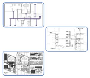
- Plumbing Plan
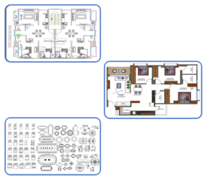
- Furniture Layout
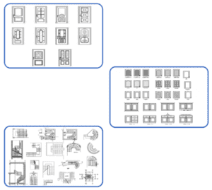
- Door Window Staircase Details
- HVAC (High Voltage Air Conditioning) Planning
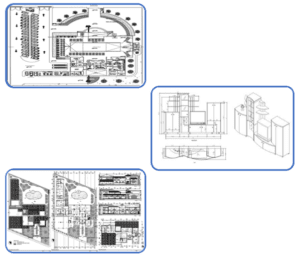
- Draft Complex Structures
- Printing Plotting
- Units & Drawing Creation
- Creating Section Line
- Creating Dimensions
- Modify Dimensions
- Dimension Style
3D Modelling & Visualization
- Introductions to 3D
- Working in 3D
- Creation of 3D door, window, staircase, railing
- Creating Solid Primitive
- Solid Model Creation from 2D Profile
- Creation of 3D model from plan
- Use of user coordinate system
- Object Creation
- Modification of Solid Models
- Editing Solid Models
- Elevation modelling
- Interior modelling
- Creating interior accessories
- Applying Material & texture
- Using Material
- Modify Material
- Adding Lights and camera
- Applying animations
- Creation of walk through
- Surface Modelling
- Using Light
- Using Render Settings
- Rendering 3D objects
- Exterior rendering
- Interior rendering
- Motion Path Animation
- Plotting Viewport & Sheet Manager
AutoCAD Productivity Tools
- Blocks And Dynamic Blocks
- Using Blocks & Block Editor
- Standard Library & Attributes
- Object Selection Method & In ternate Features
- Slide Show
- Animation 2D & 3D
- Customization of AutoCAD
- Object Grouping
- Linking File (external reference)
- Customization Of Screen
- Tool Palette and Design Center
- Government Project Norms.
- Licensing For Drawing
- PWD Norms
- State PWD Norms
- Contract And Tendering
- Estimation And Costing
- Construction And Project Management
- Site Supervision
- Land Development
- Building Design With 3D Printing
Duration :
- 60-hour theory
- 30-hour practical
- 50-hour project work with 2 case study
AutoCAD 2D Drafting:
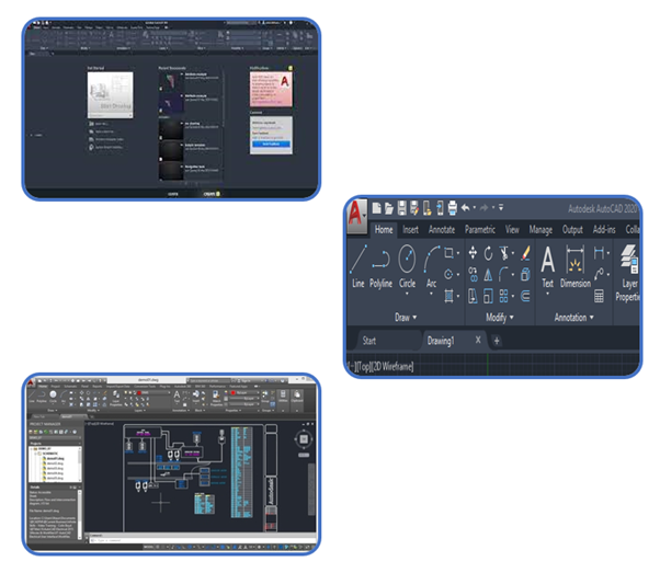
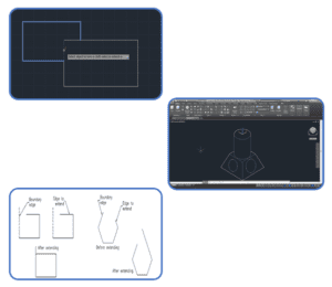
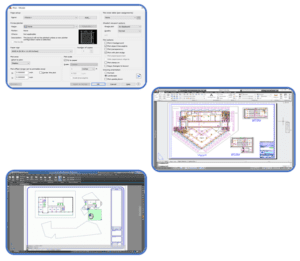
AutoCAD user interface
Understanding AutoCAD User Interface
Whether you just started using AutoCAD, or you are already an experienced user, you are likely not fully aware of all user interface elements. The same applies to AutoCAD commands. Let us review the user interface elements in AutoCAD as well as some AutoCAD commands that can give you a shortcut that will improve your workflow. AutoCAD Interface
- Application Menu
- Quick Access Toolbar (QAT)
- Ribbon
- In-Editor elements
- Status Bar
- File Tabs
- Layout Tabs
- Drop-Down Menus
- Toolbars
- Command Line
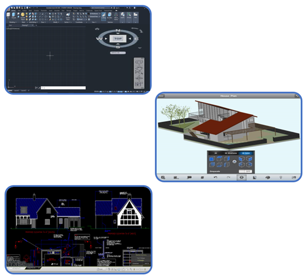
Navigating the working environment
The navigation bar is a user interface element where you can access both unified and product-specific navigation tools.
- View Cube
- Steering Wheels
- Show Motion
- 3Dconnexion
- Pan
- Zoom tools
- Orbit tools
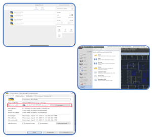
Working with files
On the homepage, also known as the file manager, you can open, upload, manage, and download files, create new folders and drawings, and connect to cloud storage providers.
- Create new drawing
- Create new folder
- To rename or delete a file or folder
- To move or duplicate a file
- Download to Offline
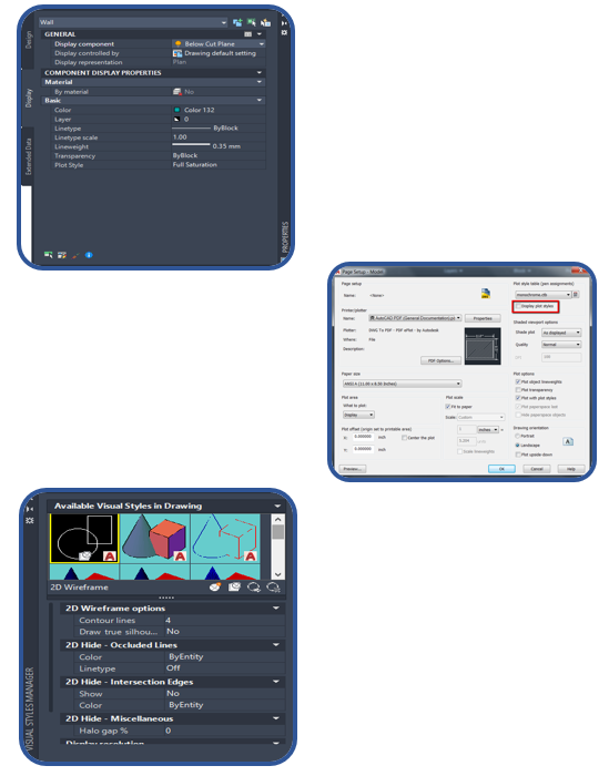
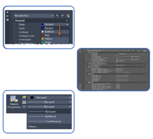
Displaying objects
- Layers
- The Layer Command
- Creating a New Layer
- Setting Color and Line type “By Layer”
- Setting the Color of a Layer
- Setting the Line type of a Layer
- Loading Line types
- Making a Layer the Current Layer
- Controlling Layer States
- Turning Layers on and Off
- Freezing and Thawing Layers
- Turn Off or Freeze?
- Locking and Unlocking Layers
- Layers in Viewports
- Renaming a Layer
- Deleting a Layer
- Purging Layers and Line types
- Colours
- The Line type Command
- Setting the Line type Scale
- The Properties Command
- The Match Properties Command
- Editing with the Object Properties Toolbar
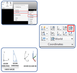
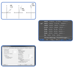
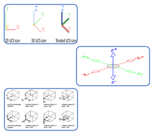
Co-ordinate system
There are two coordinate systems in AutoCAD.
- World Coordinate System (WCS)
- User Coordinate System (UCS)
which define the angle of the XY plane you are working in. The WCS should always be used to reference geometry to ensure everything aligns to the center of a file in real-world location. The UCS can be used to orientate the screen to a site.Drawing files will usually have the WCS set by default.The current WCS or UCS orientation is indicated by the UCS icon in the bottom left corner of the screen.
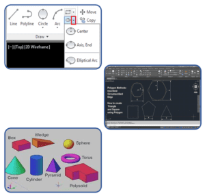
Creating basic shapes
In AutoCAD home page there are different option that is used to create object easily like-
- Line
- Circle
- Rectangle
- Arc
- Polyline
- polygon
- Box etc.
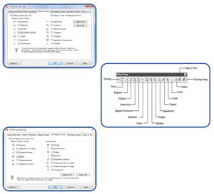
Using object snap
You can specify an object snap whenever you are prompted for a point. By default, a marker and a tooltip are displayed when you move the cursor over an object snap location on an object. This feature, called Auto snap, provides visual confirmation that indicates which object snap is in effect.
- End point
- Mid-point
- Center point
- Nearest point
- Intersection
- Tangent etc.
Creating special shapes
With the help of different commands, we can create special shapes
- Building geometry
- Elevation
- section
- 3d model
Using Polar Tracking and Polar Snaps
Polar tracking restricts cursor movement to specified angles. Polar Snap restricts cursor movement to specified increments along a polar angle. When you create or modify objects, you can use polar tracking to display temporary alignment paths defined by the polar angles you specify.
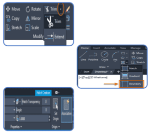
Modification of Objects
When creating technical drawings, once certain geometry is created it can be reused to build other related geometry. The modify tools will then be used to adjust this geometry to suit its purpose.
- Offset
- Erase
- Layer
- Trim
- Extend
- Explode
- Polyline edits
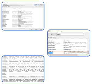
Creating Different Types of Lines
There are two options to create customized line type in AutoCAD: Create a own line type in file manually, then load it into AutoCAD in the Line type Manager. Create line type using Express Tools.
Line types can be a pattern of dashes, dots, text, and symbols, or unbroken and continuous.
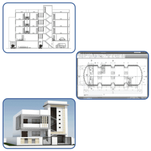
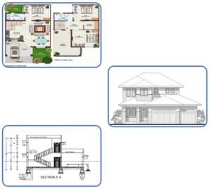
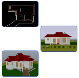
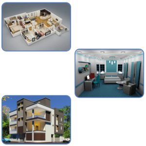
Creation Of Plan, Elevation, Section View
Plan Drawing-There are different types of plan drawings:
- Plan
- Plan Callout or Blow Up Plan
- Plan Detail
- Site Plan
- Roof Plan
- Reflected Ceiling Plan or RCP
- Plan Perspective
Elevation Drawing– There are different types of Elevation Drawings:
- Elevation
- Interior Elevation
- Elevation Call Out
- Elevation Detail
Section Drawing-There are different types of section drawing-
- Section
- Section Callout or Blow Up Section
- Plan Detail
- Site Plan
- Reflected Ceiling Plan or RCP
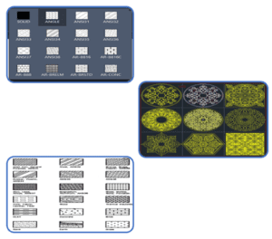
Apply Hatch & Gradient
The Hatch command in AutoCAD is used to fill patterns inside an enclosed area. The patterns are hatched, gradient, and solid fill. The gradient patterns are defined as a smooth transition between two colors. There are several hatch patterns available in AutoCAD. We can choose the desired pattern from the list of the patterns according to the requirements. The number of hatch lines represented in any pattern can be adjusted with the help of the Hatch Pattern Scale. The Hatch Pattern Scale signifies the spacing between the lines in a particular pattern.
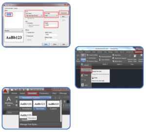
Use Of Text, Mtext & Layers
There are two kinds of text that can be used in AutoCAD: Multiline and Single Line.
You have more control over the appearance of Multiline Text and if you move the text, multiple lines stay grouped together. Single Line text is useful for writing out a collection of notes; each return creates a separate entity. This is useful for writing out multiple single line notes, such as room names, that can be moved around the screen independently from each other.
- Multiline text
- Style
- Annotation scale
- Formatting
- Background mask
- Paragraph
- Insert
- Inserting symbols
- Spell check
Object Creation & Modification
There Are Many Commands in AutoCAD (Like: Line, Circle, Arc, Fillet, Move, Scale, Rotate Etc.) Which is Used to Creta an Objects (Like: Door, Windows, Furniture Etc.)
- 2d Objects
- 3d Objects
- Drawings
- Blocks
- Geometries

Creating Object Pattern
In software engineering, creational design patterns are design patterns that deal with object creation mechanisms, trying to create objects in a manner suitable to the situation. The basic form of object creation could result in design problems or in added complexity to the design.
Trimming and Extending Objects
The Trim command in AutoCAD is used to remove the objects, which meet the edges of other objects. It is used to remove extra lines or extra parts of an object.
Object Property Tools
Object properties differentiate objects from other objects. The basic properties of an object are those items identified by its four-part name (name, type, instance, and version) and also include owner, status, platform, and release.
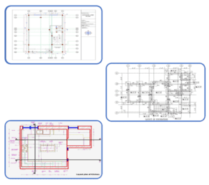
Create Foundation Plan of Structure
The Foundation Plan Is A Plan View Drawing, In Section, Showing The Location And Size Of Footings, Piers, Columns, Foundation Walls, And Supporting Beams. A Foundation Plan Ordinarily Includes the Following: • Footings for Foundation Walls, Piers, And Columns (Hidden Lines)

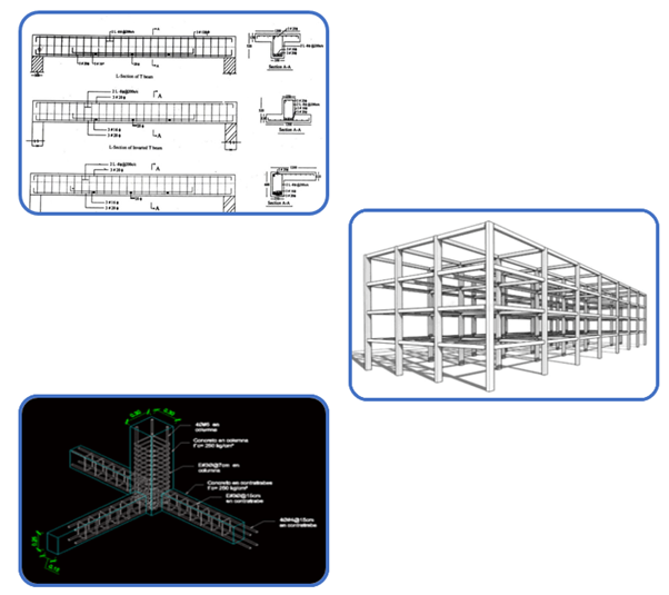
Draft Structural Drawing
The beam is a horizontal structural component that mainly carries vertical loads.
- Simply supported beam
- Continuous beam
- Over hanging beam
- Cantilever beam
- Fixed End beam
- Reinforced concrete beam
- Steel beam
- Composite beam
The columns are vertical compression members that span from substructure to superstructure and have a vital role in transferring load from the top of the structure to the foundation.
- Square column
- Circular column
- Rectangular column
- T shape column
- L shape column
- Reinforced concrete column
- Steel column
- Composite column
Creating Centre Line Plan
center layout is primarily used in structure design and construction to plan out the best possible housing of physical structure and resources in the project. As the structure center layout planning is expensive, center layout planning prior to implementation can help center designers in understanding and evaluating the space consumed.
- It has distance between two column c/c.
- Size of footing
- Size of column
- Placing of column & footing
Architectural Plan
Architectural Plans means a two-dimensional representation reflecting a proposed development/redevelopment of an enclosed/ semi-enclosed or open area showing features or elements such as-Columns, Walls, Partitions, Ceiling, Stairs, Doors, Windows, Floors, Roof, Room, Designations, Door And Window, call-outs, the architectural layout of equipment, furnishings, furniture and the like, specifications callouts, elevation references, drawing references and the like; the architectural plan is the representation of a lateral section for a proposed building/ structure (running parallel to the ground) and at a height of from 1.0 – 1.5 meters above the finished floor; the term may also collectively refer to other architectural designs such as cross/ longitudinal sections, elevations, roof plan, reflected ceiling plan; detailed sections and elevations showing architectural interiors, detailed architectural designs, door and window schedules, other architectural finishing schedules and the like.
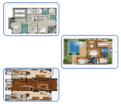
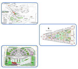
Site Plan
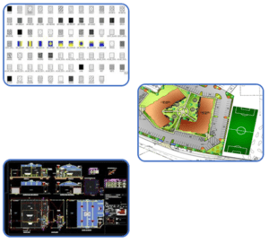
A site plan, also known as a block plan is a diagram that depicts proposed changes to your land. A site plan is significant because it offers information about the landscape elements of a particular lot.
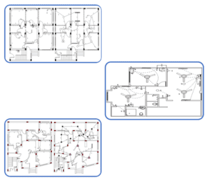
Electrical Planning
Electrical design software is used by systems designers for planning and creating electrical equipment, addressing specific workflows. Electrical design software such as AutoCAD allows electrical engineers to design integrated systems in a fraction of the time normally required when creating the process by hand.
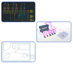
Plumbing Plan
Plumbers CAD is the only CAD software built expressly for use by Plumbers to create ‘As-Built’ drawings (also known as ‘As-Constructed’ or ‘As-Installed’ plans). Based on our most popular CAD software, Real CAD, you’ll be able to rapidly edit existing CAD drawings or create your own from scratch.
Furniture Layout
Autodesk’s AutoCAD software is one of the most well-known options for 3D modelling. It has a wide variety of applications, including furniture design.
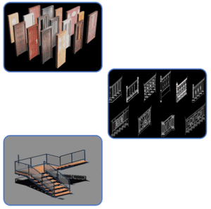
Door Window Staircase Details
AutoCAD drawing of various door window designs with respective plan and elevations. Drawing contains details of Flush doors, Glass Door, Glass Windows.
HVAC (High Voltage Air Conditioning) Planning
AutoCAD can design and model physical objects in manufacturing as well as create 2D plans of entire buildings and landscapes for civil and HVAC engineers.
Design Master HVAC is a complete ductwork drafting and calculation software program that works directly inside AutoCAD and Bricks CAD. Define the parameters of your project as you draft, then perform calculations within the software using those parameters.
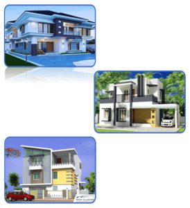
Draft Complex Structures
AutoCAD is commonly used in the construction and architectural industries a computer aided software drafting program used for creating blue print for buildings, bridges and structures.
- Bridges
- Roads
- Foundation
- Column And Beam
- Architecture Plan
Printing Plotting
You can create any plan or drawing with the help of AutoCAD then the final Output of your drawing layout to a printer, a plotter, or a file is known as printing & plotting.You can Save and restore the printer settings for each layout.
Originally, people printed text from printers and plotted drawings from plotters. Now, you can do both with either.
Units & Drawing Creation
The units are used to represent the dimensions in AutoCAD.
- Architectural Units.
- Decimal Units.
- Engineering Units.
- Fractional Units.
- Scientific Units.
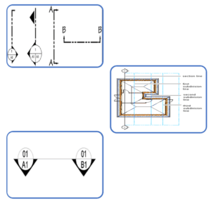
Creating Section Line
one of a series of thin parallel lines placed on the cut surfaces of section views (as in an architectural drawing)
You draw a section line by specifying a start point, an endpoint, a length, and a height for the section. You can specify additional points between the start point and the endpoint to create jogs in the section.
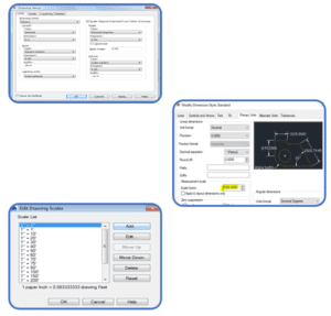
Creating Dimensions
AutoCAD annotation is what makes a project have all its meaning and its raison to the eyes of someone looking at it when the creator of the project is not around. Annotations can also help CAD drafters keep track of all the important information a plain image cannot express in a project.
3D Modelling & Visualization:
Introductions to 3D
AutoCAD 3d is a powerful CAD software, which is made use of for the architectural style and mechanical design. It has one of the best toolboxes and features to sustain 2D drawings. Nevertheless, when it involves a 3D layout, it is impressive, with its 3D providing attribute that offers sensational and vivid outputs.
Working in 3D
AutoCAD enables the professional creation and editing of 2D geometry and 3D models with solids, surfaces, and objects.
You can convert 2D sketches into 3D models. You can import a 2D drawing directly into a sketch in a part document for conversion into a 3D model. To create a base feature from a 2D drawing, extract sketches to specify the appropriate views.
Creation of 3D door, window, staircase, railing
We Can Create 2d Drawings of Door, Windows, And Staircase as Well as We Cam Create 3d Model Of Those Components In AutoCAD With Required Dimensions.
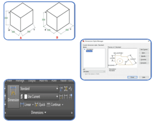
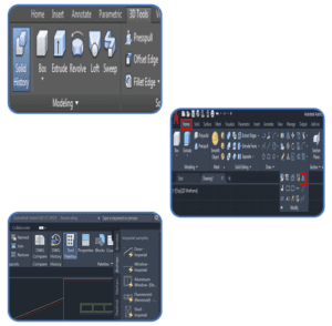
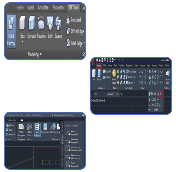
Creating Solid Primitive
A primitive solid is a ‘building block’ that you can use to work with in 3D. Rather than extruding or revolving an object, AutoCAD has some basic 3D shape commands at your disposal. From these basic primitives, you can start building your 3D models. In many cases, you get the same result from drawing circles and rectangles and then extruding them, but doing it one command is generally faster. Using these with Boolean operations can be a very effective way of drawing in 3D. There are eight different primitives that you can choose from and are on the Home > Modeling Tool Panel (when in the 3D workspace).
Creation of 3D model from plan
3D modelling is the process of using software to create a mathematical representation of a 3-dimensional object or shape. The created object is called a 3D model and these 3-dimensional models are used in a variety of industries.
- Building modelling
- Interior modelling
- Exterior modelling
Use of user coordinate system
The User Coordinate System (UCS) is the coordinate system used to construct 3D models. It can be located at the WCS or at any location or orientation in 3D space. Being able to locate and orientate the UCS anywhere in 3D space is the secret of 3D modelling.
Elevation modelling
The elevation line defines the extents of the elevation view of your building model. Elevation lines can be straight or jogged. You can also specify the length and the height of the area defined by the elevation line.
A 2D or 3D elevation is created from the elevation line properties and the selected objects in the building model. The elevation is linked to the building model.
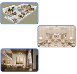
Interior modelling
3D interior design is the representation of a fully furnished and decorated room including lighting, textures and materials from a 3D perspective.
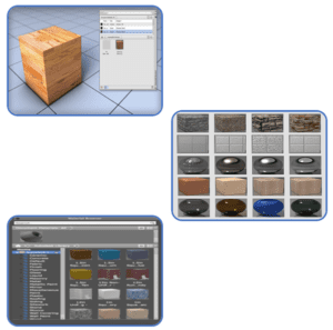
Applying Material & texture
Each Texture Type Has a Unique Set of Controls, Or Channels, That Adjust Such Properties as Reflectivity, Transparency, And Self-Illumination. Within Each These Channels, You Can Assign, Hide, Or Delete A Texture. When You Assign Textures to A Material’s Color, The Texture Colors Replace the Material’s Diffuse Color.
- Wood Texture
- Wall Paints
- Floorings
- Ground Texture
- Metal Materials
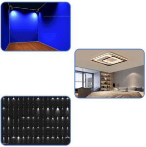
Adding Lights and camera
Default lighting is derived from one or two distant light sources that follow the viewpoint as you orbit around the model. All faces in the model are illuminated so that they are visually discernible. You can adjust the exposure of the rendered image, but you do not need to create or place lights yourself.
The Camera tool is located in the Camera panel on the Visualize ribbon. The Camera panel contains only two tools: Create Camera and Camera Display. You use the Create Camera tool to create and place cameras into the drawing, and the Camera Display tool to toggle the visibility of camera glyphs on and off.
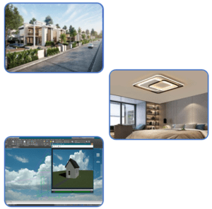
Rendering 3D objects
In computer-aided design (CAD), a rendering is a particular view of a 3D model that has been converted into a realistic image. It includes basic lighting such as Girouard shading as well as more sophisticated effects that simulate shadows, reflection and refraction.
- Exterior Rendering
- Interior Rendering
- 360 View of Interior
- Walkthrough Video
AutoCAD Productivity Tools:
- Blocks And Dynamic Blocks
- Using Blocks & Block Editor
- Standard Library & Attributes
- Object Selection Method & In ternate Features
- Slide Show
- Animation 2D & 3D
- Customization of AutoCAD
- Object Grouping
- Linking File (external reference)
- Customization Of Screen
- Tool Palette and Design Center
- Government Project Norms.
- Licensing For Drawing
- PWD Norms
- State PWD Norms
- Contract And Tendering
- Estimation And Costing
- Construction And Project Management
- Site Supervision
- Land Development
- Building Design With 3D Printing
Upcoming Batches
Certifications

Civil AutoCAD Certification Training
About Civil AutoCAD Certification Training in Indore at Tech Cluster