AutoCAD is a versatile and most ubiquitous commercial Drafting & Modeling software tool developed and marketed by AUTODESK since 1982. AutoCAD is an essential tool for High School Students, Technical Students, Draftsmen, Diploma Engineers, Mechanical, Automobile Engineers, and Corporate Managers and is used by over 10 million users worldwide.
Tech Cluster is an institute which provides AutoCAD training in Indore and offers chances to avail a great opportunity to learn the tool from basic to advanced level. Our expert faculties cover all the important factors of AutoCAD Training for beginners and intermediates. With our expert guidance students can excel in their career and earn good. After which you can find good opportunities in MNC Industries like Eicher and other automobile industries.
Applications
Aerospace calls their final design as an assembly.
Automotive call their final design a Parts design.
Electrical and electronics call their final design as Blueprint and Circuit design.
Rail and marine call their final design as Layout or Blueprint.
Structural and civil call their final design as Layout.
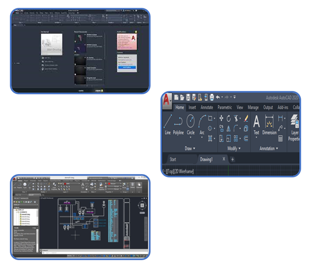
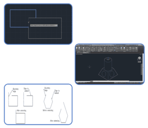
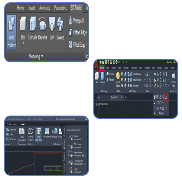
Whether you just started using AutoCAD, or you are already an experienced user, you are likely not fully aware of all user interface elements. The same applies to AutoCAD commands. Let us review the user interface elements in AutoCAD as well as some AutoCAD commands that can give you a shortcut that will improve your workflow. AutoCAD Interface
Application Menu
Quick Access Toolbar (QAT)
Ribbon
In-Editor elements
Status Bar
File Tabs
Layout Tabs
Drop-Down Menus
Toolbars
Command Line
Navigating the working environment
The navigation bar is a user interface element where you can access both unified and product-specific navigation tools.
View Cube
Steering Wheels
Show Motion
3Dconnexion
Pan
Zoom tools
Orbit tools
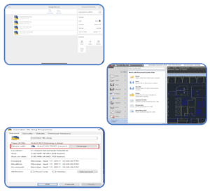
Working with files
On the homepage, also known as the file manager, you can open, upload, manage, and download files, create new folders and drawings, and connect to cloud storage providers.
Create new drawing
Create new folder
To rename or delete a file or folder
To move or duplicate a file
Download to Offline
Displaying objects
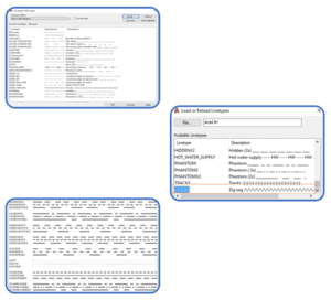
Layers
The Layer Command
Creating a New Layer
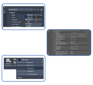
Setting Color and Line type “By Layer”
Setting the Color of a Layer
Setting the Line type of a Layer
Loading Line types
Making a Layer the Current Layer
Controlling Layer States
Turning Layers on and Off
Freezing and Thawing Layers
Turn Off or Freeze?
Locking and Unlocking Layers
Layers in Viewports
Renaming a Layer
Deleting a Layer
Purging Layers and Line types
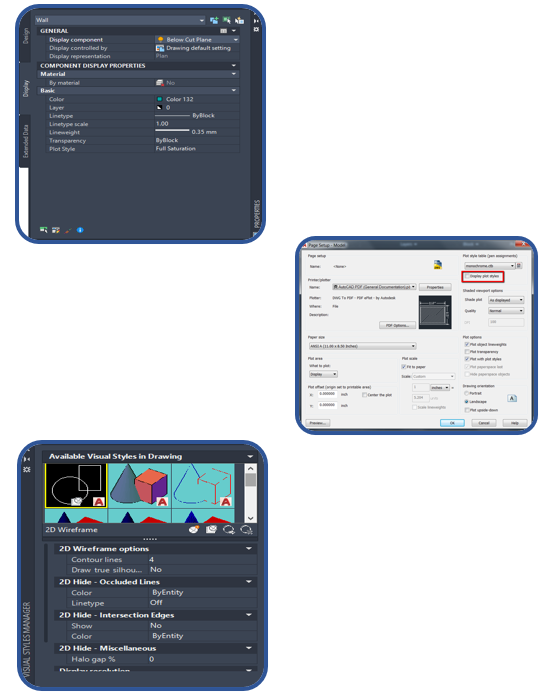
Colours
The Line type Command
Setting the Line type Scale
The Properties Command
The Match Properties Command
Editing with the Object Properties Toolbar
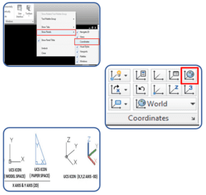
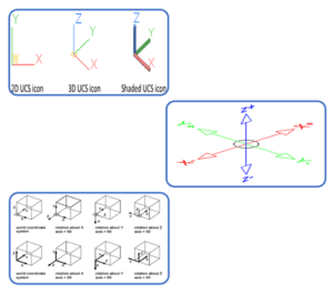
Co-ordinate system
There are two coordinate systems in AutoCAD.
World Coordinate System (WCS)
User Coordinate System (UCS)
which define the angle of the XY plane you are working in. The WCS should always be used to reference geometry to ensure everything aligns to the center of a file in real-world location. The UCS can be used to orientate the screen to a site.Drawing files will usually have the WCS set by default.The current WCS or UCS orientation is indicated by the UCS icon in the bottom left corner of the screen.
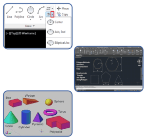
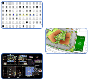
Creating basic shapes
In AutoCAD home page there are different option that is used to create object easily like-
Line
Circle
Rectangle
Arc
Polyline
polygon
Box etc.
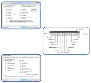
Using object snap
You can specify an object snap whenever you are prompted for a point. By default, a marker and a tooltip are displayed when you move the cursor over an object snap location on an object. This feature, called Auto snap, provides visual confirmation that indicates which object snap is in effect.
End point
Mid-point
Center point
Nearest point
Intersection
Tangent etc.
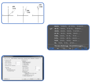
Using Polar Tracking and Polar Snaps
Polar tracking restricts cursor movement to specified angles. Polar Snap restricts cursor movement to specified increments along a polar angle. When you create or modify objects, you can use polar tracking to display temporary alignment paths defined by the polar angles you specify.
Modification of Objects
When creating technical drawings, once certain geometry is created it can be reused to build other related geometry. The modify tools will then be used to adjust this geometry to suit its purpose.
Offset
Erase
Layer
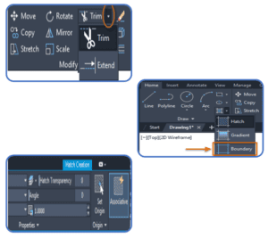
Trim
Extend
Explode
Polyline edits
Creating Different Types of Lines
There are two options to create customized line type in AutoCAD: Create a own line type in file manually, then load it into AutoCAD in the Line type Manager. Create line type using Express Tools.
Line types can be a pattern of dashes, dots, text, and symbols, or unbroken and continuous.
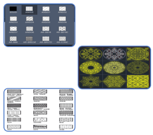
Apply Hatch & Gradient
The Hatch command in AutoCAD is used to fill patterns inside an enclosed area. The patterns are hatched, gradient, and solid fill. The gradient patterns are defined as a smooth transition between two colors. There are several hatch patterns available in AutoCAD. We can choose the desired pattern from the list of the patterns according to the requirements. The number of hatch lines represented in any pattern can be adjusted with the help of the Hatch Pattern Scale. The Hatch Pattern Scale signifies the spacing between the lines in a particular pattern.
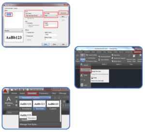
Use Of Text, Mtext & Layers
There are two kinds of text that can be used in AutoCAD: Multiline and Single Line. You have more control over the appearance of Multiline Text and if you move the text, multiple lines stay grouped together. Single Line text is useful for writing out a collection of notes; each return creates a separate entity. This is useful for writing out multiple single line notes, such as room names, that can be moved around the screen independently from each other.
Multiline text
Style
Annotation scale
Formatting
Background mask
Paragraph
Insert
Inserting symbols
Spell check
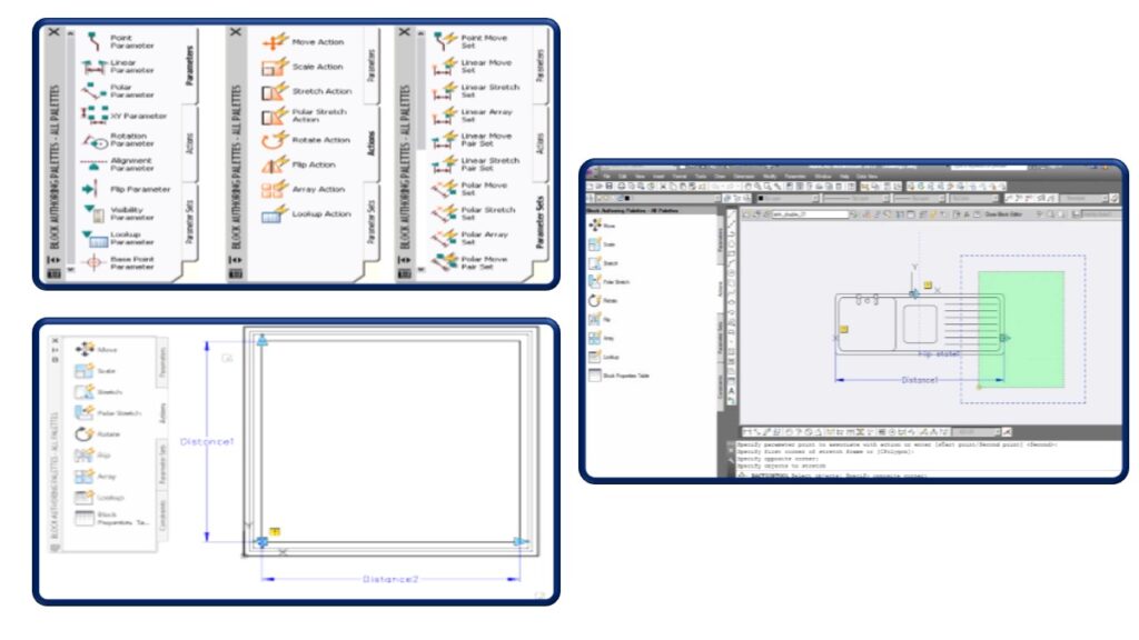
Creating Object Pattern
In software engineering, creational design patterns are design patterns that deal with object creation mechanisms, trying to create objects in a manner suitable to the situation. The basic form of object creation could result in design problems or in added complexity to the design.
Trimming and Extending Objects
The Trim command in AutoCAD is used to remove the objects, which meet the edges of other objects. It is used to remove extra lines or extra parts of an object.
Object Property Tools
Object properties differentiate objects from other objects. The basic properties of an object are those items identified by its four-part name (name, type, instance, and version) and also include owner, status, platform, and release.
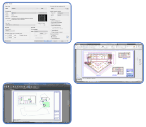
Printing Plotting
You can create any plan or drawing with the help of AutoCAD then the final Output of your drawing layout to a printer, a plotter, or a file is known as printing & plotting.You can Save and restore the printer settings for each layout.
Originally, people printed text from printers and plotted drawings from plotters. Now, you can do both with either.
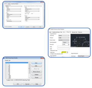
Units & Drawing Creation
The units are used to represent the dimensions in AutoCAD.
Architectural Units.
Decimal Units.
Engineering Units.
Fractional Units.
Scientific Units.
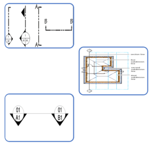
Creating Section Line
one of a series of thin parallel lines placed on the cut surfaces of section views (as in an architectural drawing)
You draw a section line by specifying a start point, an endpoint, a length, and a height for the section. You can specify additional points between the start point and the endpoint to create jogs in the section.
AutoCAD 3d is a powerful CAD software, which is made use of for the architectural style and mechanical design. It has one of the best toolboxes and features to sustain 2D drawings. Nevertheless, when it involves a 3D layout, it is impressive, with its 3D providing attribute that offers sensational and vivid outputs.
Working in 3D
AutoCAD enables the professional creation and editing of 2D geometry and 3D models with solids, surfaces, and objects.
You can convert 2D sketches into 3D models. You can import a 2D drawing directly into a sketch in a part document for conversion into a 3D model. To create a base feature from a 2D drawing, extract sketches to specify the appropriate views.
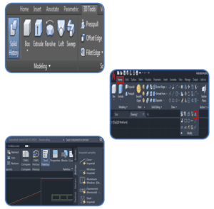
Creating Solid Primitive
A primitive solid is a ‘building block’ that you can use to work with in 3D. Rather than extruding or revolving an object, AutoCAD has some basic 3D shape commands at your disposal. From these basic primitives, you can start building your 3D models. In many cases, you get the same result from drawing circles and rectangles and then extruding them, but doing it one command is generally faster. Using these with Boolean operations can be a very effective way of drawing in 3D. There are eight different primitives that you can choose from and are on the Home > Modeling Tool Panel (when in the 3D workspace).
Use of user coordinate system
The User Coordinate System (UCS) is the coordinate system used to construct 3D models. It can be located at the WCS or at any location or orientation in 3D space. Being able to locate and orientate the UCS anywhere in 3D space is the secret of 3D modelling.
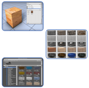
Applying Material & texture
Each Texture Type Has a Unique Set of Controls, Or Channels, That Adjust Such Properties as Reflectivity, Transparency, And Self-Illumination. Within Each These Channels, You Can Assign, Hide, Or Delete A Texture. When You Assign Textures to A Material’s Color, The Texture Colors Replace the Material’s Diffuse Color.
Wood Texture
Wall Paints
Floorings
Ground Texture
Metal Materials
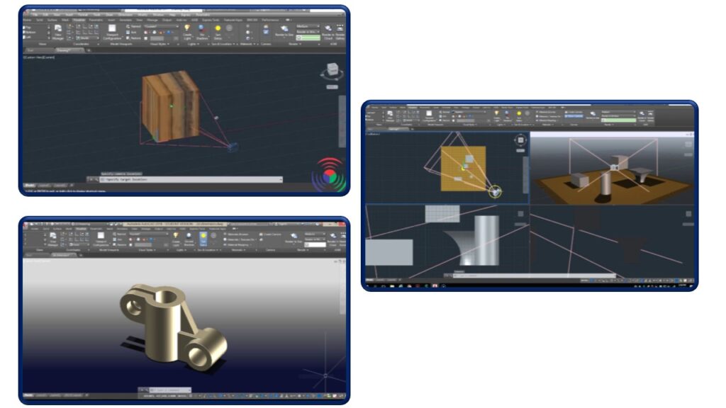
Adding Lights and camera
Default lighting is derived from one or two distant light sources that follow the viewpoint as you orbit around the model. All faces in the model are illuminated so that they are visually discernible. You can adjust the exposure of the rendered image, but you do not need to create or place lights yourself.
The Camera tool is located in the Camera panel on the Visualize ribbon. The Camera panel contains only two tools: Create Camera and Camera Display. You use the Create Camera tool to create and place cameras into the drawing, and the Camera Display tool to toggle the visibility of camera glyphs on and off.
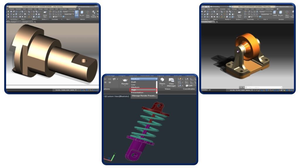
Rendering 3D objects
In computer-aided design (CAD), a rendering is a particular view of a 3D model that has been converted into a realistic image. It includes basic lighting such as Girouard shading as well as more sophisticated effects that simulate shadows, reflection and refraction.