Surface design plays an imperative role in the making of a strong backbone. A designer must have a distinct set of purposes and design strategies well-known to secure that part design is cost effective and can be easily manufactured. Function, attachment method, mechanical properties, and developed properties should be considered over before moving well into the design cycle. Tech Cluster is an institute which provides Surface design training in Indore and offers chances to avail a great opportunity to learn the tool from basic to advanced level. Our expert faculties cover all the important factors of Surface design Training for beginners and intermediates. With our expert guidance students can excel in their career and earn good. After which you can find good opportunities in MNC Industries like Eicher and other automobile industries.
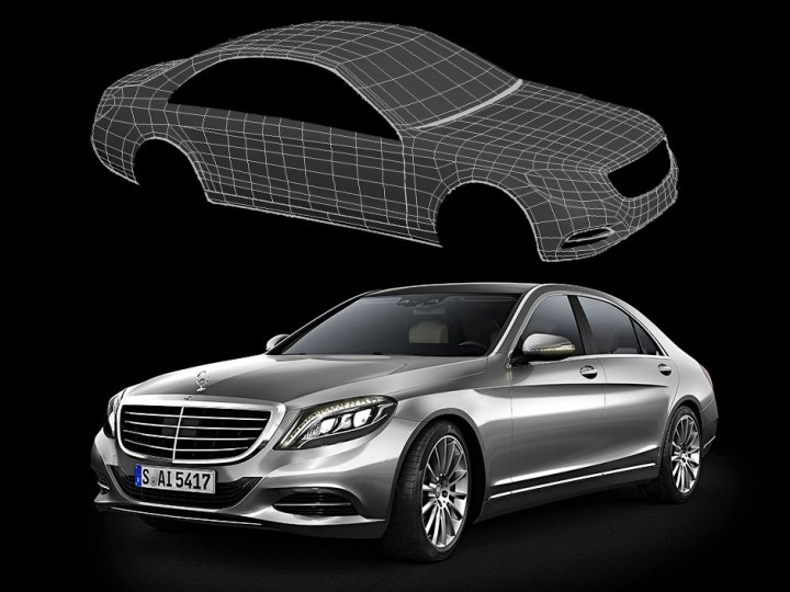
A wire frame model consists only of edges of surfaces or lines of intersection of surfaces but does not contain information about the areas between the lines. For a 3D surface model, you must define the surfaces mathematically. Several other surfaces, such as cylinders and spheres, have mathematical expressions that can be written to describe them. Most real surfaces cannot be defined by a single mathematical expression. In some cases, it may be adequate to break the non-plane surface into a large number of plane facets.
Wire-Frame Geometry
The construction techniques used for the definition of wire-frame geometry are again broadly similar to those for drawing, but with certain extensions. One that has already been mentioned is the use of movable work coordinate systems, and in general a number of ways of defining WCS from existing points or from existing coordinate systems are provided. Some examples of methods offered by one CAD system. Associated with the WCS are the concepts of the work plane and the working depth. Often, planar entities such as arcs and conic sections are constructed by default in a plane (the work plane) parallel to the X-Y plane of the WCS at a Z-axis value equal to the working depth. The work plane is also used for projected intersections and points: it is often useful to be able to use apparent intersections of entities when viewed along the z-axis, even though the entities may not physically intersect in space. In such cases the intersection points are projected into the work plane.
Wire-frame modeling
Very often designers also build physical models to help in the visualization of a design. This may require the construction of ‘skeleton’ models using wires to represent the edges of an object or component. Wireframe modeling, as used currently in computer-aided engineering techniques, is the computer-based analogue of this process, and is used not only to model objects but also to facilitate the production of various projected views to aid visualization.
Wire-frame representation
A wire-frame representation of a three-dimensional object consists of a finite set of points and connecting edges, which define the object ‘adequately’ and facilitate subsequent visualization. The term ‘edge’ does not necessarily imply that it is a straight-line segment. An edge may well be an arc of a circle or any other well-defined space curve, which is required for a ‘good’ wire-frame representation.
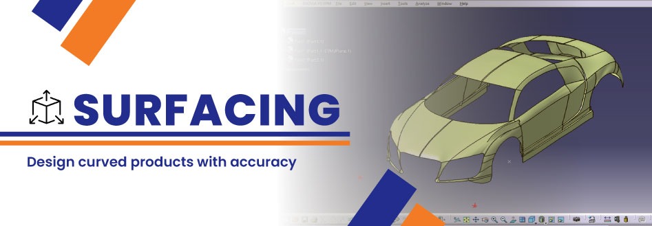
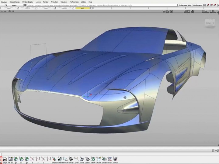
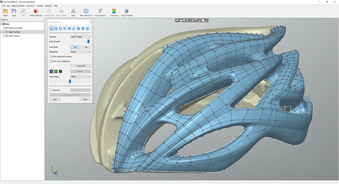
Surfacing Methods
Surfacing methods are divided into two categories – solid based creation techniques and manual surface creation tools. These techniques create solid parts and features directly, much like Extrude command, only using more than one section in the definition.
The second category of surfacing tools is manual techniques to create surfaces from wire frame geometry. These tools will require more steps to create solid parts from the bottom up, starting with wire frame geometry to create surfaces, and using surfaces to create solids.