Gear Box Design Training in India
- Real-Time Experts Sessions
- LIVE Project
- Certification
- Affordable Fees
- Flexibility
- Placement Support
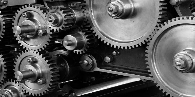
A gear is fundamental element of Engineering industry and many of the modern house hold equipments. Gears & Gear boxes have successfully used in Automotives, Aircrafts, Space Crafts and many other common applications like fans, Clocks, Pumps, Motors etc since ages. Nevertheless there has been a gap between the educators, Manufacturers and the users of the gears & gear boxes. There has been a consistence lack of knowledge in the gear industry which resulted into many failures, often maintenance problems all adding to high cost solutions.
Tech Cluster has sensed this gap and realized that there is an imminent need for developing a course on Gear Box Design to cater to the technicians, Engineers in gear Manufacturing and marketing industry.
This course is also highly useful to budding engineers to get an hands on training on gear design Simulation,3D Molding, Analysis, Optimization, Manufacturing and assembly techniques the course’s main objectives is to develop the students into entrepreneurs in gear industries
Course Highlights:
Gear Box Design Foundation :
- History & Evolution of Gears
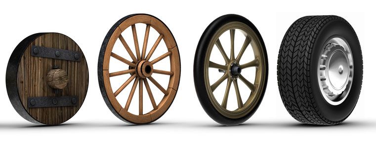
- Inventions of Wheel
- Relevance of Gears to Mankind
- Industrial Revolution and the growth of Gears
- Applications of Gear & Gear Boxes
- Design of Gears
- 3D Modeling, Analysis, Simulation of gears
- Types of Gears
- Material Used in the Gears
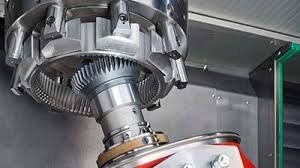
- Manufacturing Techniques for Gears
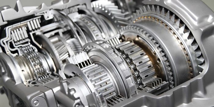
- Design of Automotive Gear Box
- Reverse Engineering of the five geared Gear Box
- Assembly/Disassembly of five geared Gear Box
Duration :
- 45 Hours Theory
- 45 Hours Practical
- 20 Hours Project work
Technical Features:
History & Evolution of Gears
Aristotle has the credit to his name of giving the earliest description of gears in the 4th century B.C. According to his definition, the direction of rotation is reversed when one ear wheel drives another gear wheel. Gears have been used by the Greek Inventors in water wheels and clocks. The sketches of various types of gears of this time can be found in the notebooks of Leonardo da Vinci.
Even after these ground-breaking discoveries, no major development concerning wheels was made until the 17th Century. In this time, first attempts were made to provide constant velocity ratios. These attempts utilized the involute curves. This was just the beginning of something that changed the world for all the good reasons. However, in the 19th century, form cutters and rotating cutters were first used and it was then in 1835 when the English inventor Whitworth patented the first gear hobbing process.
Inventions of Wheel
The wheel was invented in the 4th millennium BC in Lower Mesopotamia(modern-day Iraq), where the Sumerian people inserted rotating axles into solid discs of wood. It was only in 2000 BC that the discs began to be hollowed out to make a lighter wheel.
This innovation led to major advances in two main areas. First, transport: the wheel began to be used on carts and battle chariots. Second, and more importantly, it contributed to the mechanization of agriculture (animal traction, crop irrigation) and craft industries (for example, the centrifugal force of the wheel is the basic mechanism in windmills).
Relevance of Gears to Mankind
Relevance of Gears to Mankind is as follows-
- Power: Energy companies of all types use gears in their machines and plants. Oil and gas corporations use the gears of worms, worm gears, and worm gear reducers manufacturers to speed up or slow down their drills and other tools. Power plants rely on turbines for generating power, and these turbines require a variety of custom gears and gearboxes. Even green energy benefits from gears, with wind turbine gears for wind power and pinions adjusting the angle of solar panels for solar power. Mining companies also need gears for their digging and excavation equipment, in order to extract coal.
- Cars: The automotive industry requires specific worm gear designs for the steering components of their vehicles. Worm gear reducers manufacturers provide reducers for slowing a vehicle’s speed. Engines rely on well-greased gears for moving all of their parts, so gear manufacturers are an essential partner in this industry. And when you hear the phrase “shifting gears,” there really are gears at work helping your car to move!
- Utilities: and Mass Transit: Infrastructure and transportation sectors also use several different types of gears. The infrastructure system requires gears for machinery to maintain quality roads, sewers, and electrical grids, among other purposes. Public transportation vehicles and trains use gears in engines, on train and subway cars, and in the switches along the tracks.
- Manufacturing: In factories and food processing plants, conveyor belts are a common fixture. They help move parts down a line, and they aid in the packaging and shrink wrapping of foods and consumer goods. From printing jobs to large-scale production, many facilities rely on gears to keep things moving.
Applications of Gear & Gear Boxes
- Metal cutting machines.
- Power plants.
- Mechanical clocks and watches.
- Fuel pumps
- They are used in automobiles.
- Gearboxes
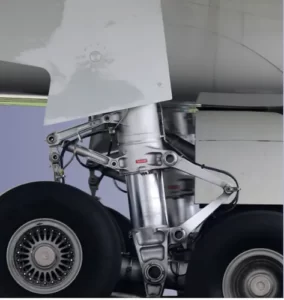
- Aerospace industries.
- Textile industries.
- Bevel gears are used where power transmission at right angles is required.
- Widely used in gearboxes.
- Used in the packaging industry.
- Electric motors.

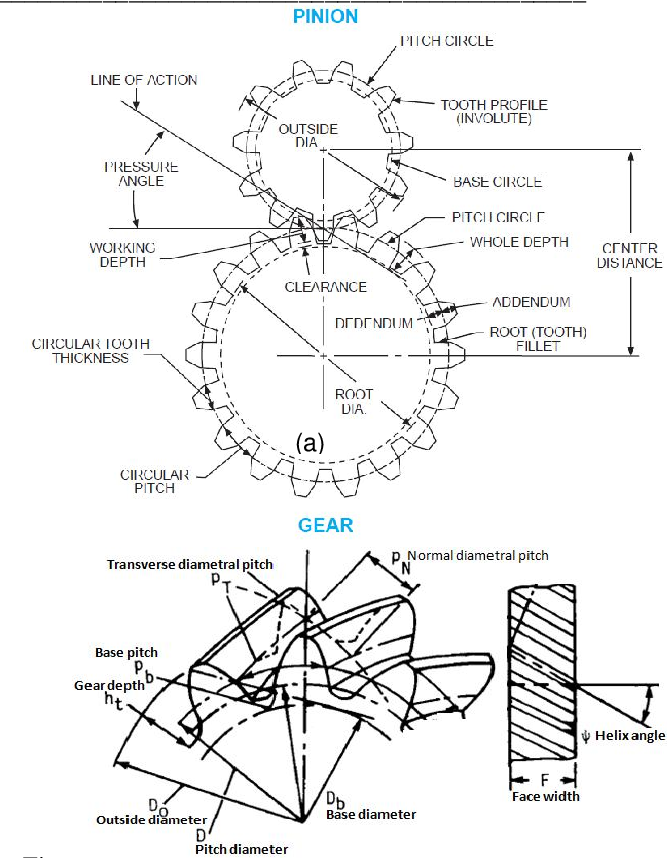
Design of Gears
The main conditions of Gear Design are-
Dimensional considerations – mainly related to space restrictions of the machine design
- Center distance of the shafts
Normally gears matching the center distance between the shafts is used, but there are occasions when profile shifting is used. - Available space for mounting gears
The decisions on tooth widths and outside diameters are affected by this. Normally various elements of mechanism within the interior of the machine are placed to utilize space efficiently. Therefore, these tooth widths and outside diameters can be restricted by the machine’s design itself.
Amount and direction of force considerations – mainly related to the required performance of gears
- The amount of force transmission and the required strength of gears
Chiefly conditions affecting bending and tooth surface strengths which are determined by material, pitch, pressure angle, profile shifting amount, tooth width, heat treating methods, etc. - Direction of force transmission
Affects the decision of tooth helix direction and type of gears (e.g. use of racks for linear motion). - Desired speed ratio
Determined by the choices of numbers of teeth.
Usage and handling considerations
- Durability of gears
Since it is mostly determined by the bending and tooth surface strengths, it influences the decision on material, pitch, pressure angle, profile shifting amount, tooth width, heat treating methods, etc. Also it affects the lubrication method. - Related to the weight and maintainability
Determines mainly the size, form, material (specific gravity), and method of shaft attachment. - Related to noise and vibration
Affects the decisions chiefly on precision grade, need for tooth grinding, use of crowning or end relief, material, amount of backlash and lubrication method. - Related to shock at start and stop time
Related to gear strength so that it is influenced by material, pitch, pressure angle, profile shifting amount, tooth width, heat treating methods, etc. It is also affected by the amount of backlash.

3D Modeling, Analysis, Simulation of gears
- Gear Dynamic Modeling
- Simulation and Experiment
- Dynamic Behavior Analysis
Spalling Fault Simulation

Types of Gears
- Spur Gears
- Helical Gears
- Herringbone Gears
- Bevel Gears
- Miter Gear
- Hypoid Gears
- Sprockets
- Face Gear
- Worm Gears
- External Gears
- Internal Gear
- Rack and Pinion
- Epicyclic Gears
- Involute splines
- Straight Sides Splines

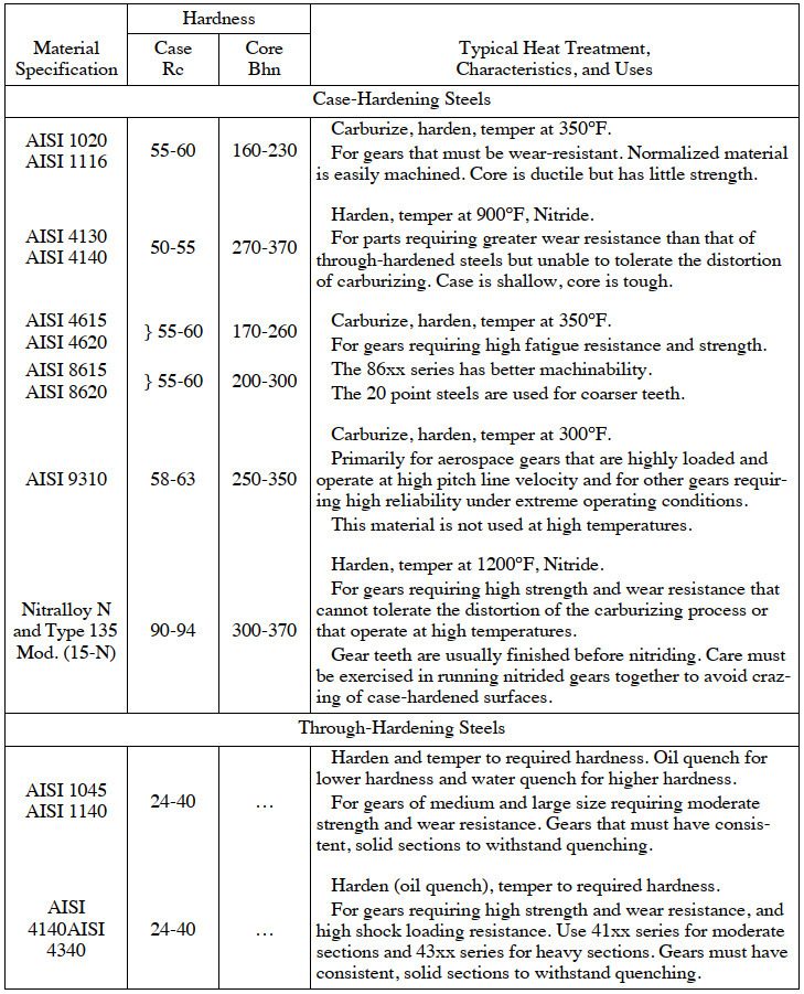
Material Used in the Gears
Criteria for Gear Materials
First, you have to consider the core “necessities” for most gear materials:
- High tensile strength. If you use a material with a low or insufficient tensile strength, you could experience a failure when dealing with static loads. Static loads exert a consistent amount of force over time.
- High endurance. If you use a material will low or insufficient endurance, you could experience a failure when dealing with dynamic loads. Dynamic loads change pressure or force over time.
- Low friction coefficient. Because gears are moving parts in a complex system, they need to be made of materials that aren’t particularly susceptible to the effects of friction.
- Manufacturability. Finally, the material needs to be malleable and capable of being manipulated. Otherwise, we wouldn’t be able to cut the gear. There’s an endless number of different materials that can be used to create gears, but as a general rule, cast iron, steel, brass, bronze and plastic are the most common materials used for gears with cut teeth.
Manufacturing Techniques for Gears
Here are three types of processes involved in gear manufacturing:
- Gear Broaching – This process is generally done to manufacture steel shafts and splines. It’s used in order to fashion the gear into a leveled structure while removing excess material from it. The broach is key to defining the odd shapes of particular gears, and is also used to help define the strange shapes of some gears types.
- Gear Hobbing – Gear hobbing is used to manufacture smaller gears as well as sprockets and splines. These gears cannot be accommodated by broaching. Circular-shaped hobbing machines are surrounded by teeth. These type of machines are mainly used in the manufacturing of helical gears, spur gears and many other small gears.
- Gear Machining – CNC machining is actually used in the manufacturing of gears with extreme precision and accuracy. This process is usually done by an experienced machinist. Gear machining is used to manufacture a number of products, including internal gears, worm gears, sprockets, spur and helical gears.
Design of Automotive Gear Box
Follow this procedure to have an idea about how to design a complete Gear Box with each component’s design.
- Determine the maximum and minimum speeds of the output shaft. This will determine the complete speed ratio. Calculate the number of steps or speed reduction stages for this range. This depends on the application as well as space optimization. Higher reduction stages require more space because of more number of gears and shafts requirements. This can be a limitation for automobiles to keep car bodies less bulky.
- Select the type of speed reducer or gearbox based on the power transmission requirements, gear ratio, positions of the axis, and space available for the speed reducer. Also, make sure that for low gear ratio requires single-speed reduction. One can select worm gears for silent operation and bevel gears for intersecting axis.
- Determine the progression ratio which is the ratio of maximum speed and minimum speed of the output shaft of the Gear Box. The nearest progression ratio should be a standard one and is taken either from the R 20 or R 40 series. You can refer to the design data book for this task.
- Draw the structural diagram and kinematic arrangement indicating various arrangement possibilities during speed reduction or increment.
- Select materials for gears so that gear should sustain the operating conditions and operating load. Normally cast iron is chosen for housing and cast steel or other alloy can be selected as per the load requirements.
- Note down the maximum power output in Horse Power (H.P) or transmission power and revolution per minute of short i.e. rpm of each shaft.
- Determine the center distance between the driven and driver shaft based on the surface compressive stress.
- Determine the module of gear by beam strength as well as fix the number of teeth required.
- Calculate the diameter of the shafts by torque requirements and bending moment considerations.
- Calculate the key size, shape, or type of transmission keys for each gear.
- Select appropriate fit and tolerance for mating parts like shaft and gear.
- Select bearings types based on the loading and operating conditions. The bearing can be selected based on load and speed. Also, make sure to include consideration of maximum speed and expected life of gears and gearboxes. Normally ball bearings and roller bearings are used for the small size of the gearbox because they have lower thrust requirements due to low-speed reduction.
- Make the shaft step or provide a collar to prevent axial displacement of bearing and gear.
- Provide suitable clearance between gears and walls of the housing of a gearbox and based on these considerations design the casing/housing of the gearbox.
- Complete the design of the casing. One should Provide fins if necessary to have increased heat transfer by convection and conduction. Put inspection hole/manhole as well as a drain hole to drain lubricating oil. Also, provide an oil level indicator to have the proper amount of oil during operation, if not put, this will lead to failure of gear and shaft due to overheating or due to frictional failure. Provide transportation hooks for transporting the gearbox from one place to another or during installation and maintenance. Also, design the gear changing lever accordingly.
- Draw neat and clean working drawings in suitable software like AutoCAD, Pro-Engineer, etc., indicating required details during manufacturing or assembly.
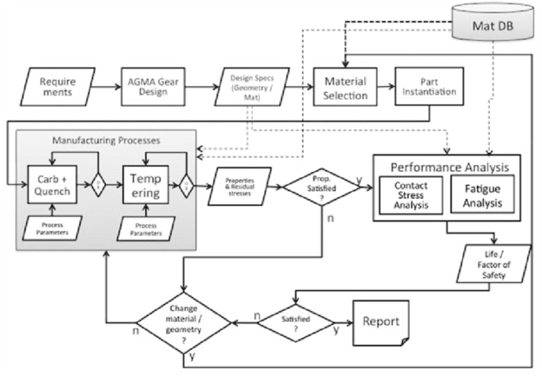
- One can also perform finite element analysis of the complete Gear Box after it completely designed.

Upcoming Batches
Certifications

Gear Box Design Certification Training
About Gear Box Design Certification Training in Indore at Tech Cluster