CNC Machining Training in India
- Real-Time Experts Sessions
- LIVE Project
- Certification
- Affordable Fees
- Flexibility
- Placement Support
Computer numerical control (CNC) is the numerical control system in which a dedicated computer is built into the control to perform basic and advanced NC functions.CNC controls are also referred to as soft- wired NC systems because most of their control functions are implemented by the control software programs. CNC is a computer assisted process to control general purpose machines from instructions generated by a processor and stored in a memory system.
Tech Cluster is an institute which provides CNC Machine Training and offers chances to avail a great opportunity to learn the tool from basic to advanced level. Our expert faculties cover all the important factors of CNC Machine Training for beginners and intermediates. With our expert guidance students can excel in their career and earn good. After which you can find good opportunities in MNC Industries like Eicher and other automobile industries.
Course Highlights:
CNC Machine Foundation :
- History and Definition of CNC
- Mechanics of CNC
- CNC Coordinates
- Basics of the CNC Machining Center
- CNC Specs for the Mill
- Design of 3 Axis CNC Machine
- Design of the Guide ways for X,Y,Z axes
- Milling Calculations
- 3D Modeling of the machine
- Selection of the drives, Spindle
- Design of control system
- Selection of control cards
- Manufacturing the parts of CNC machine
- Developing the CNC Machine
- Working with a CAM Programs
- Writing A CNC G – Code
Duration :
- 45 Hours Theory
- 45 Hours Practical
- 20 Hours Project work
Technical Features:
History and Definition of CNC
- Computer numerical control (CNC) is the numerical control system in which a dedicated computer is built into the control to perform basic and advanced NC functions.
- CNC controls are also referred to as soft- wired NC systems because most of their control functions are implemented by the control software programs.
- CNC is a computer assisted process to control general purpose machines from instructions generated by a processor and stored in a memory system.
Mechanics of CNC
Contemporary CNC machines are fully automated. All they need is digital files with the instructions about cutting trajectories and tooling.
Design or machining processes require many tools to produce a certain part. Machinists can build digital tool libraries that interface with the physical machine. Such machinery can automatically switch tooling based on the digital instructions, making them manufacturing workhorses.
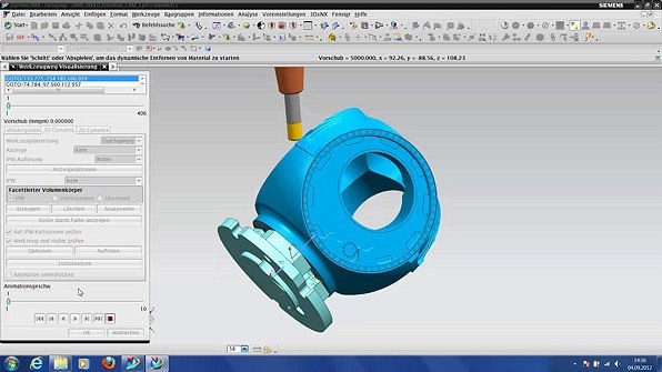
The CNC machining process starts with designing the parts in CAD software. The 3D model determines the necessary dimensions and properties of the final part.
Some of these programs come in CAD-CAM packages, so the flow can continue in the same programs. Otherwise, CAD models are fed into designated CAM software. If both CAD and CAM are from the same product family, no translation of files is necessary. Otherwise, the CAD files need to be imported.
CAM (computer-aided manufacturing) software prepares the model for the whole fabrication process. First, it checks the model for errors. Then it creates a CNC program to fabricate the physical part.
The program is, in essence, a set of coordinates that guides the cutting head during the manufacturing process.
The third step is choosing the right parameters. These include cutting speed, voltage, RPMs, etc. The configuration depends on the geometry of the part as well as the available machinery and tooling.
Lastly, the software determines the nesting. Nesting means the orientation and placement of parts relative to raw material. The purpose is to maximize the material usage.
All this information is then translated into codes that the machinery can understand – M-code and G-code.
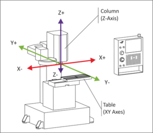
CNC Coordinates
Using the Cartesian coordinate system, we control CNC machines along each axis to transform a block of material into a finished part. Although it’s difficult to describe axes using relative terms, based on each axis, you typically get the following movements from the perspective of an operator facing the machine:
- X-axis allows movement “left” and “right”
- Y-axis allows movement “forward” and “backward”
- Z-axis allows movement “up” and “down”
Put all of this together, and you have a CNC machine that can cut various sides of a workpiece in the XY plane and at various depths along the Z axis.
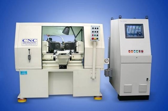
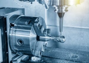
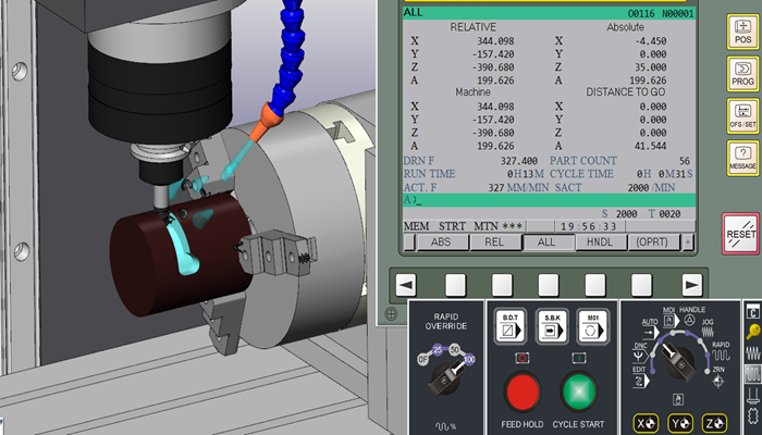
Basics of the CNC Machining Center
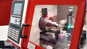
The CNC machine center (cnc turning center) is an advanced manufacturing machine tool. Machinery can perform various machining operations. The types and functions of the CNC Machining Center are introduced below.
The CNC machine tool center (machine centre) is an advanced manufacturing machine tool that can perform a variety of machining operations with high precision, high quality, and high surface finish. A CNC machine tool center (CNC turning center) can perform drilling, milling, and lathe operations.
The manufacture of prismatic parts in the industry, such as gearboxes, partitions, frames, covers, etc., requires different types of operations such as milling, boring, drilling, tapping and many other related machining operations. In the past, this production process had to be divided into many working stages, and the operation on different machine tools was able to produce a finished product, which was resulted in a large amount of delivery time and cost. To overcome this problem, a CNC machine tool center was developed. Milling, lathing, and drilling operations on a single machine tool allows one machine to perform a greater variety of machining needs.
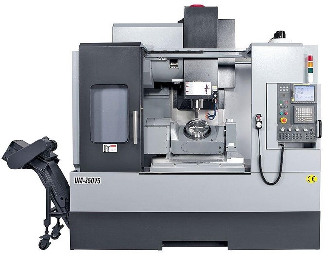
Configuration classification type of CNC machining center:
- Horizontal Machine Center
- Vertical Machine Centers
- Universal Machining Center
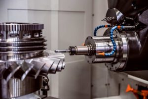
CNC Specification for the Mill
CNC milling is a machine process which produces custom-designed parts or components by progressively removing material from the workpiece using rotating multi-point cutting tools and computerized controls. These systems usually have three linear degrees of freedom. They can move freely around the X, Y, and Z axes while the workpiece remains stationary. This limited dimensional operation reduces the speed of operations, making milling more suitable for prototyping and smaller production runs
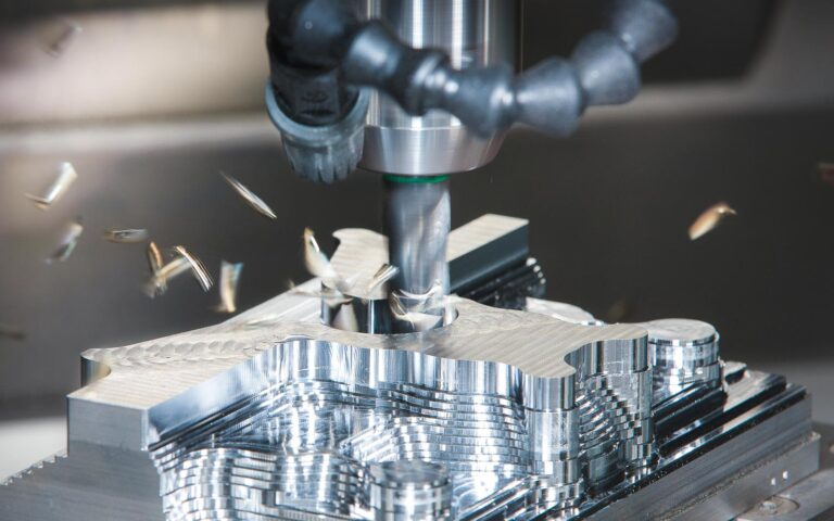
Design of 3 Axis CNC Machine
3 axis machining implies that the workpiece remains in the same position while the cutting tool operates along the XYZ plane to trim away material. This is suitable for parts that don’t require a lot of depth and detailing. 3 axis machining is most commonly used to produce mechanical components and is best suited for:
- Automatic/interactive operation
- Milling slots
- Drilling holes
- Cutting sharp edges

Milling Calculations
A CNC process called milling creates slots, helical grooves or flat surfaces on vertical, inclined or horizontal planes. In this case, the CNC machining time estimation may use a feed rate that’s per tooth, meaning you need to know the number of flutes, teeth or cutting edges on the specific tool you have.
When using the original formula for assistance — Machining Time = Length of Cut (mm) / Feed (mm per revolution) x Revolutions Per Minute — the calculation for CNC milling machining time equals Machining Time = Length of Cut (mm) x Number of Passes / Feed (mm per revolution) x Revolutions Per Minute, with the specifications being:
- Length of Cut (mm) = Tool Approach + Job Length + Tool Over Travel + Compulsory Distance
- Feed (mm per revolution) = Feed Per Tooth x Number of Teeth
- Revolutions Per Minute = 1,000 x Cutting Speed / π x Diameter of Rod (mm)
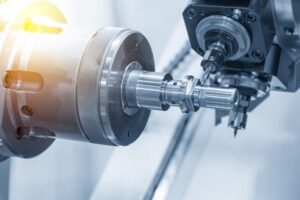
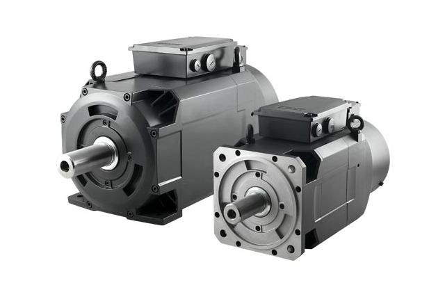
Selection of the drives, Spindle
A machine spindle is a critical component, and is needed in a wide array of industries, including the automotive and aerospace sectors. Spindles are electrically or air-powered devices that come in numerous sizes.
Typically, there is a shaft that holds the tool together, a motor, and a taper used to control various tools. Then, the spindle rotates on an axis. The axis is controlled by commands coming from either a person or a computer. As the machine rotates the tool, the spindle cuts, slices, refines, and more.
CNC spindles come in many shapes and forms, but they are typically divided into two categories, each of which has its own set of benefits.
- Integral Motor Spindle
- Belt-Driven Spindle
Design of control system
The architecture of modern control systems is based around digital signal processing and the use of a bus to connect the various components. Highly integrated electronic circuits (ASICs) are used, enabling the size of the control to be minimized. The CNC consists of the following main components:
- Operator panel based on industry-compatible PC technology for the man/machine interface (MMI)
- CNC control unit (NCU)
- Programmable controller (PLC)
- Drive modules for machine tool axes and spindles (feed drives VSA, and main spindle drive HSA)
- Motors (AC motors and linear drives)
- Supply and energy recovery unit (S/E unit)
As each drive module, the NCU, the PLC and the operator’s panel each contain a processor, a modern CNC can also be seen as a multiprocessor system.
Design of 3 Axis CNC Machine
3 axis machining implies that the workpiece remains in the same position while the cutting tool operates along the XYZ plane to trim away material. This is suitable for parts that don’t require a lot of depth and detailing. 3 axis machining is most commonly used to produce mechanical components and is best suited for:
- Automatic/interactive operation
- Milling slots
- Drilling holes
- Cutting sharp edges
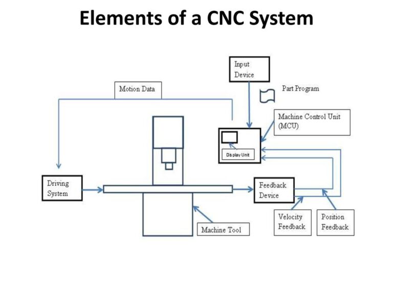
Developing the CNC Machine
The primary components of a CNC machine are represented by the following:
- The Input Device
- Machine Control Unit
- Machine Tools
- The Drive System
- Feedback Mechanism
- Display Unit
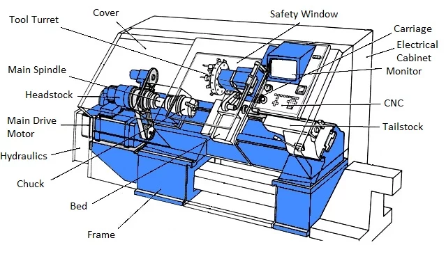
- Bed
- Headstock
- The Tailstock
- Tailstock Quill
- Pedal or a Footswitch
- Chuck
- The Control Panel
Working with a CAM Programs
CAM software prepares a drawing for production, which is considered the last step in the design process. For that reason, you can think of CAM software as “slicer software” that translates drawings and data into detailed instructions to drive an automated tool.
CAM software uses G-code to communicate directly with the control machine. As a programming language generated from a drawing, this G-code “instructs” the tool on what to do. For example, it will tell the motors where to move, how fast to move, and the programmed path they should follow.
Behind the scenes, CAM software does a few things:
- Error checking: CAM software checks whether the model has any geometrical errors that can affect the manufacturing process.
- Toolpath generation: The toolpath is a set of given coordinates that the machine is required to follow during the machining process. A good example would be setting a cutting sequence.
- Device configuration: Before operation can begin, machine parameters like voltage, cutting speed, and pierce height must be adjusted. Different programs can set different parameters, but once these parameters are defined automatically, the machine operator’s job will be simplified.
- Optimization: In consideration of all of these details, CAM software attempts to identify the best orientation to maximize efficiency.
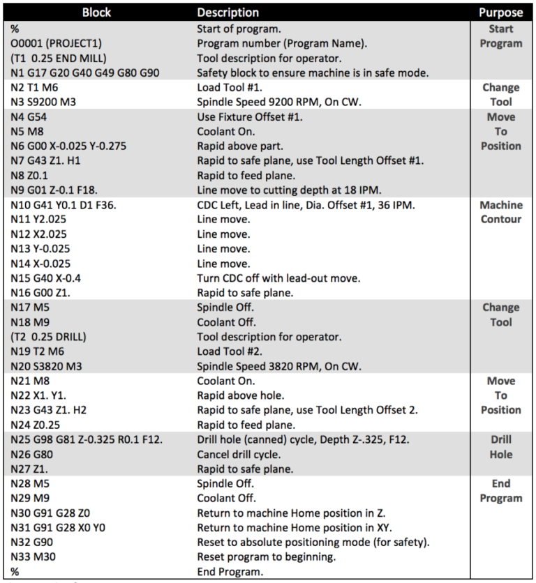
Writing A CNC G – Code
G-Code Program
The goal of every G-code program is to produce parts in the safest and most efficient way possible. To achieve this, you’ll typically find G-code blocks arranged in a particular order like this:
- Start the CNC program.
- Load the required tool.
- Turn the spindle on.
- Turn the coolant on.
- Move to a position above a part.
- Start the machining process.
- Turn the coolant off.
- Turn the spindle off.
- Move away from the part to a safe location.
- End the CNC program.
Upcoming Batches
Certifications
CNC Machining Certification Training
About CNC Machining Certification Training in Indore at Tech Cluster