A PROGRAMMABLE LOGIC CONTROLLER (PLC) is an industrial computer control system that continuously monitors the state of input devices and makes decisions based upon a custom program to control the state of output devices.
Almost any production line, machine function, or process can be greatly enhanced using this type of control system. However, the biggest benefit in using a PLC is the ability to change and replicate the operation or process while collecting.
Tech Cluster is an institute which provides PLC training in Indore and offers chances to avail a great opportunity to learn the tool from basic to advanced level. Our expert faculties cover all the important factors of PLC Training for beginners and intermediates. With our expert guidance students can excel in their career and earn good. After which you can find good opportunities in MNC Industries like Eicher and other automobile industries.
Introduction to PLC hardware and Role in Automation
PLC’s act as the physical interfaces between devices on the plant or manufacturing floor and a SCADA or HMI system. PLCs communicate, monitor and control automated processes like assembly lines, machine functions, or robotic devices.
A PLC’s functions are divided into three main categories: inputs, outputs and the CPU. PLCs capture data from the plant floor by monitoring inputs that machines and devices are connected to. The input data is then processed by the CPU, which applies logic to the data, based on the input state. The CPU then executes the user-created program logic and outputs data or commands to the machines and devices it is connected to.
PLC Fundamentals - (Block diagram of PLC's)
The block diagram of PLC consists of different components. Each component has associated specific functions and operations in the PLC.
The list of basic components are.
Input and Output Modules
Power Supply
Control Processing Unit (CPU)
Memory System
Communication Protocols
Programming
Types of Inputs & outputs / Source Sink Concepts
The Input modules gather data from all field input devices and transmit it to the PLC processor (CPU) as voltage or current signals. The received signals are the PLC inputs. The CPU then processes the received information as pre-programmed data, which it uses together with the execution results of its programmed logic to control the field output devices via the Output modules. Thus, PLC outputs are the appropriate control commands that the PLC CPU sends out to control/operate physical devices upon executing the user program from its Random-Access Memory (RAM).
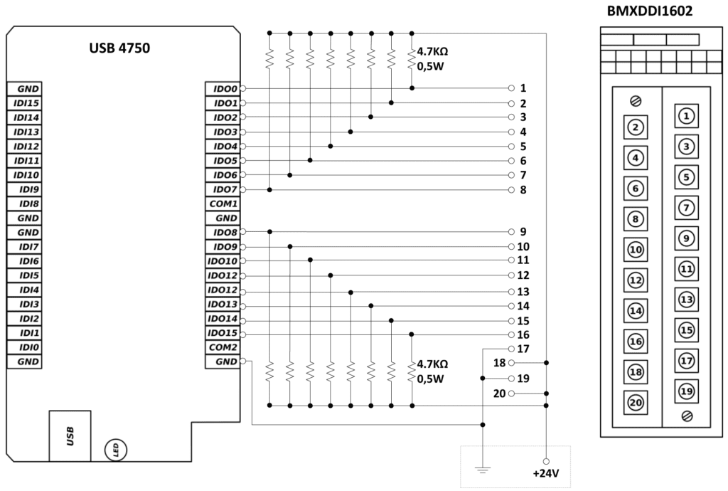
Wiring of the I/O devices
The following are ten recommended procedures for I/O wiring:
Remove and lock out input power from the controller and I/O before any PLC installation and wiring begins.
Verify that all modules are in the correct slots. Check module type and model number by inspection and on the I/O wiring diagram. Check the slot location according to the I/O address assignment document.
Loosen all terminal screws on each I/O module.
Locate the wire bundle corresponding to each module and route it through the duct to the module location.
Starting with the first module, locate the wire in the bundle that connects to the lowest terminal.
Insert the uninsulated end of the wire under the pressure plate of the terminal and tighten the screw.
If two or more modules share the same power source, jumper the power wiring from one module to the next.
If shielded cable is being used, connect only one end to ground, preferably at the rack chassis.
Repeat the wiring procedure for each wire in the bundle until the module wiring is complete.
After all of the wires are terminated, check for good terminations by gently pulling on each wire.
Concept of flags and Scan cycle execution
Flags: A flag reveals whether a data structure is in a possible state range and may indicate a bit field attribute, which is often permission-related. A microprocessor has multiple state registers that store multiple flag values that serve as possible post-processing condition indicators such as arithmetic overflow.
The command line switch is a common flag format in which a parser option is set at the beginning of a command line program. Then, switches are translated into flags during program processing.
Scan Cycle: One scan cycle after another scan cycle keeps on running until there is an interruption from a human or any failure in the PLC. The scan cycle is divided into 3 main parts. Input Scan, Program Scan, and Output Scan.
Installing and to starting the programming terminals
Programming a PLC is an incredibly important aspect of any position in industrial automation. By knowing how to accurately and quickly set up and program a PLC one can effectively streamline any industrial process. PLCs require multiple different skills from wiring to networking all the way down to a fundamental understanding of ladder logic systems.