GD&T Training Institute in India
- Real-Time Experts Sessions
- LIVE Project
- Certification
- Affordable Fees
- Flexibility
- Placement Support
Geometric Dimensioning and Tolerancing is a system for defining and communicating engineering tolerances. It uses a symbolic language on engineering drawings and computer-generated three-dimensional solid models that explicitly describe nominal geometry and its allowable variation. It tells the manufacturing staff and machines what degree of accuracy and precision is needed on each controlled feature of the part.
ISO defines GD&T as “geometrical product specifications (GPS)—Geometrical tolerancing—Tolerancing of form, orientation, location and run-out.” In short, “geometrical product specifications” refer to the shape, size, and positional relationship of a product, while “tolerance” means the allowable error. “Geometric tolerance” is characterized by a definition that includes the allowable errors for the form and position in addition to size.
Applications
- Provides a precise and consistent method for communicating design intent
- Establishes a coordinate system (that references the datum features) for inspection and manufacturing
- Reduces the need to explain complex requirements
- Facilitates and simplifies gaging requirements
- Identifies critical-to-function features
- Simplifies tolerance analysis
GD&T Course Highlights:
GD&T Foundation :
- Introduction
- Advantage of GD&T
- Feature And Rules in GD&T
- Datum Controls
- Fundamental of Routing
- Creating Routing Components
- Using P & ID files
- Tolerances in GD&T
- Adding GD&T To a Drawing/design
Duration :
- 25 Hours Theory
- 25 Hours Practical
- 20 Hours Project work
Technical Features:
Introduction
Geometric Dimensioning and Tolerancing is a system for defining and communicating engineering tolerances. It uses a symbolic language on engineering drawings and computer-generated three-dimensional solid models that explicitly describe nominal geometry and its allowable variation.

Advantage
Why is geometric tolerance necessary?
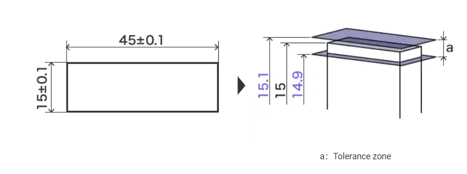
For example, when the designer orders sheet parts, the size tolerance-based instructions will be as follows:
These parts are non-conforming or defective products. These parts are produced because there is no mention of parallelism in the drawing. The fault lies with the tolerance instruction by the designer, and not with the manufacturer.
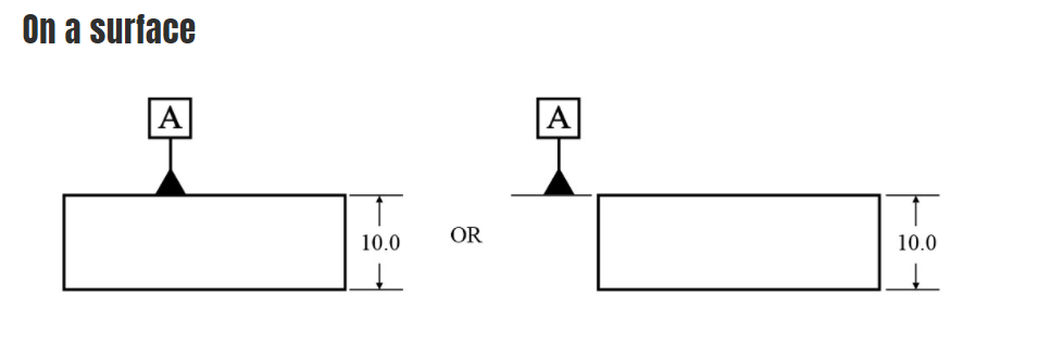
The drawing for the same part will be as follows using geometric tolerance. Here, the geometric characteristics “parallelism” and “flatness” are used in addition to size. This can prevent errors like those we saw above with size tolerance.
Geometric tolerance has the advantage of accurately and efficiently communicating the designer’s intended design in a way that cannot be expressed using size tolerance alone

Feature and Rules
- Rule -1: Rule 1 states that where only a tolerance of size is specified, the limits of size of an individual feature of size prescribe the extent to which variations in its geometric form, as well as its size, are allowed. No element of a feature shall extend beyond the MMC boundary of perfect form. The form tolerance increases as the actual size of the feature departs from MMC toward LMC. There is no perfect form boundary requirement at LMC
- Rule -2: Rule 2 states that RFS automatically applies, in a feature control frame, to individual tolerances of size features and to datum features of size. MMC and LMC must be specified when these conditions are required.

Tolerances in GD&T
- Form Tolerances
- Orientation Tolerances
- Profile Tolerances
- Location Tolerances
- Run out Tolerances

Adding GD&T To A Drawing/design
Step 1: Define Part features that would serve as origin with specific directions for measurement
- This step relates to Datums. Datums need to be selected based on the following criteria:
- Representative of Mating Features
- Reflect Functional Assembly
- Stable
- Repeatable
- Accessible
Step 2: Specify Nominal (Basic) Dimensions for Location and/or Orientation of Features from Datums
Step 3: Specify Tolerance Zone Boundaries for Part Features in terms of shape and size along with specific rules for compliance
Step 4: Allow Dynamic Interaction of Tolerance Zones between Features in a Part, and across parts, simulating Assembly possibilities for Maximizing Tolerances
Step 5: Cost of Precision Vs Cost of Poor Quality Analysis for Optimal Tolerances

Upcoming Batches
Certifications

GD & T Certification Training
About GD&T Certification Training in Indore at Tech Cluster


Reviews