


- Wooden form,
- Plywood form,
- Steel form,
- Combined wood-steel form,
- Reinforced concrete form, and
- Plain concrete form.
Slab formwork essentially supports the weight of the concrete during the curing process and when the concrete slab is positioned on permanent supports. Bases (also known as sills) are required that are made from wood or metal and these bases support the vertical stringers which in turn support the horizontal joists. The horizontal joists create a flat surface where timber, plywood, steel sheets, aluminium or fibreglass can be used as a base onto which the concrete is poured.
In most cases, formwork can be re-used and the method of removing the formwork once the concrete has been set is known as stripping. After the formwork has been stripped, it must be cleaned to ensure the faces of the panels remain straight and there is no built-up of concrete. Reusable forms are known as ‘panel forms’ while non-usable forms are known as ‘stationary forms’.
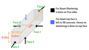 For Beam, shuttering is done in 5 sides and the other side (top side is left to fill concrete) Shuttering area can also be calculated by finding out the individual area of each faces as below: Face 1 : Area of rectangle = L x B = 0.8 x 4 = 3.2 Face 2 : Area of rectangle = L x B = 0.6 x 4 = 2.4 Face 3 : Area of rectangle = L x B = 0.8 x 4 = 3.2 Face 4 : Area of rectangle = L x B = 0.8 x 0.6 = 0.48 Face 5 : Area of rectangle = L x B = 0.8 x 0.6 = 0.48 Total Area of Shuttering = 3.2 + 2.4 + 3.2+ 0.48 +0.48 = 9.76.Sqm
To hold the concrete shuttering firmly in place and for proper alignment a concrete pad called starter is cast before fixing the shuttering. The thickness is about 45 mm to 60 mm and dimensions are precisely the same as the dimensions of proposed column. The starter should be cured for a day or 2 so that it is hard enough to fix the shuttering around it.
Column box or shuttering for columns is made of plywood sheets or steel sheets fabricated with adequate stiffeners.
A thin films of oil or grease should be applied to inner surface of the shuttering to enable easy removal of the column after the concrete hardens.
Shuttering should be properly aligned to its verticality and diagonals to be checked to ensure accuracy in dimensions.
Formwork has to be thoroughly supported with props size before pouring the concrete so that it does not moves horizontally or vertically during concreting.
The gaps near the shuttered joints should be sealed with plaster or a piece of wood to prevent any leakage of slurry.
How do I determine the classes of the props to be used correctly?
The following must be verified in order to establish whether the class and the model of the prop is functional to the execution of the work at hand: choosing a general class of prop
C (ultimate load on prop) < R (characteristic design strength)
with C given by the sum of the following values:
- Specific weight of the boards;
- Specific weight of the wood beams (transversal plus longitudinal);
- Specific weight of the chosen prop;
- Concrete load;
- Moving load.
NB:R is calculated using the formulae present in table 2 as a function of the extension lengths of the chosen prop and the height of the slab to be constructed.
How many props do I need to sustain my slab?
Upon establishing the centre-to-centre distances between the beams, the maximum distances allowed between the props, and the class/model of the props to be used, the number of props required will be simply obtainable based on the surface of the slab that they are designated to sustain.


Final setting time of cement can be defined as the time elapsed between the moments when water is added to the cement to the time when the cement paste has completely lost its plasticity. Final setting time of cement can also be defined as the time elapsed between the moments when water is added to the cement to the time when square needle makes impression on the paste, while the annular collar fails to do so.

The device which is used to find the initial setting time of cement is called as Vicat apparatus. It has a square needle of 1 mm size and 50 mm length and a mould, which is 40 mm in height and 80 mm in diameter.
Test Procedure:
- A cement paste is prepared by mixing water 0.85P% by weight of cement.
- The time of mixing should not be less than 3 minutes and should not be more than 5 minutes.
- After proper mixing the paste is filled in the vicat mould and the top surface is levelled properly.
- The mould is then placed under square needle and this needle is slowly brought down to touch the surface of the paste.
- Now the square needle is suddenly released and allowed to sink into the cement paste by its own weight.
- The depth of penetration of the square needle in the paste is noted down.
- The whole experiment is repeated with incremental time intervals until such a time when the square needle is penetrated to a depth of 33 to 35 mm from the top of the mould.
- The time elapsed between the moments when water is added to the cement to the time when the square needle penetrates a depth of 33 to 35 mm from the top of the mould is known as the Initial Setting Time of that cement.
- The initial Setting Time should not be less than 30 minutes for Ordinary Portland Cement.